
More project photos (2)
The problem
Electricity bills arrive as a single number, so nobody knows which device actually wastes power. A whole-house energy meter shows only the total — the charger left on all night, the old table fan, the room heater — every load hides inside one monthly figure. Single-outlet smart plugs solve one socket at a time, are usually locked to a vendor's cloud, and give no honest per-outlet measurement for the rest of the board. The result is that households cannot answer the basic question of where their units go, and energy-saving advice stays generic. This project builds the missing middle: a 4-outlet smart extension board where every outlet is individually switched and individually measured. Each outlet carries its own PZEM-004T energy sensor on a unique Modbus address, so voltage, current, active power and cumulative energy are read per outlet, not estimated from the total. Daily schedules run on the ESP32 itself with an NTP-synced clock, and a companion Android app gives live readings, toggles and tariff-based cost estimates over local Wi-Fi. Built from standard parts with a documented calibration procedure, it is a complete mains-interfacing IoT build a student can genuinely explain and defend.
How it works
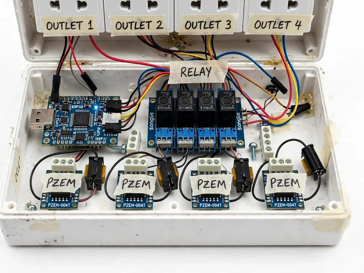
- Each of the 4 Indian 3-pin outlets is wired through its own channel of the 4-channel relay module and its own PZEM-004T sensor, each PZEM set to a unique Modbus slave address.
- The ESP32 polls the four sensors over UART (Modbus RTU) about once per second, collecting voltage, current, active power, cumulative energy, frequency and power factor per outlet.
- The firmware checks each reading against the on-device schedule table and the per-outlet overload limit; on overload it opens that outlet's relay, sounds the buzzer and publishes a trip event.
- Readings and relay states are published over Wi-Fi to the local MQTT broker, and the ESP32 exposes a lightweight HTTP API for direct outlet control.
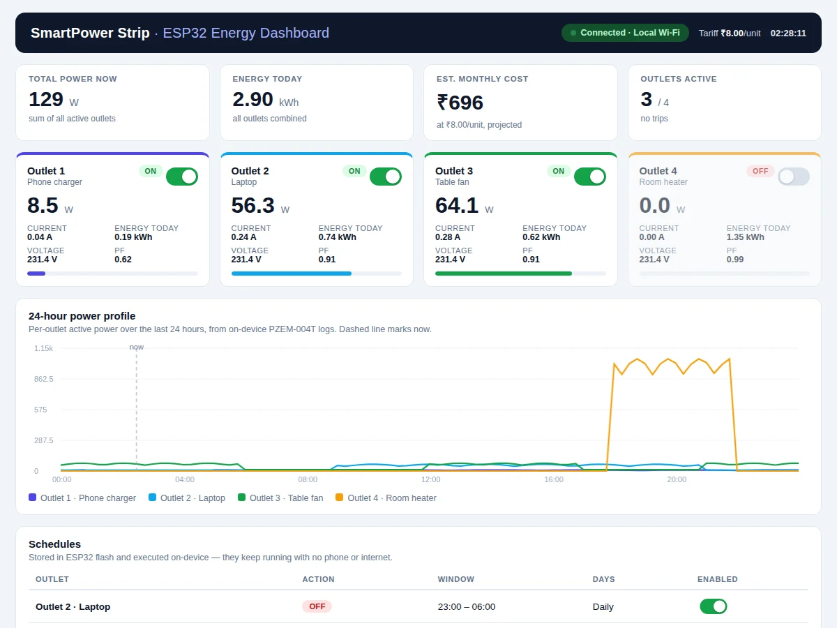
- The Android app (Kotlin) connects over the same Wi-Fi network: live per-outlet cards, on/off toggles, a schedule editor, and cost estimates computed from measured kWh and the configured tariff.
- Schedules, tariff and relay-state policy live in ESP32 flash — the strip executes timers standalone, so the app is the control surface, not a dependency.
- Before final testing, the student runs the included calibration procedure with a known reference load to verify each channel's readings and documents the result in the report.
Tech stack:
- ESP32 development board (Wi-Fi, Modbus polling, scheduling, MQTT)
- PZEM-004T energy sensor modules × 4 (one per outlet)
- 4-channel relay module (10 A 250 VAC per datasheet)
- Arduino (C++) firmware on ESP32
- MQTT (Mosquitto-class local broker) + HTTP API
- Android app in Kotlin
- NTP time sync for schedules
- HTML/JS energy dashboard (demo + report visuals)
| Parameter | Value |
|---|---|
| Outlets | 4 × 230 V Indian 3-pin sockets (design) |
| Max load per outlet | 6 A / 1380 W (design target; relay parts rated 10 A 250 VAC per datasheet, socket rating governs) |
| Energy sensing | 1 × PZEM-004T per outlet, unique Modbus address each |
| Measurement accuracy | ±1% power/energy, ±0.5% voltage/current (datasheet, not calibrated lab-grade) |
| Polling rate | Approximately 1 reading per outlet per second (expected) |
| Control latency | Outlet toggle under 1 s over local Wi-Fi (expected) |
| Scheduling | Daily timers on-device, NTP-synced; survive power cuts via flash |
| Overload cut-off | Configurable, default 6.5 A per outlet (design target) |
| Input protection | Fused mains inlet (design); not a substitute for MCB/ELCB |
| Connectivity | 2.4 GHz Wi-Fi, local MQTT + HTTP API; cloud/remote access optional (configurable) |
| Companion app | Android (Kotlin) source + installable APK |
Project features
- [Per-outlet energy measurement] Each of the 4 outlets has its own PZEM-004T module on a unique Modbus address, measuring voltage, current, active power, cumulative energy (kWh), frequency and power factor for that outlet alone. Nothing is inferred from the total — this is what separates the build from a whole-house meter or a single smart plug.
- [Per-outlet relay switching] A 4-channel relay module (10 A 250 VAC per datasheet) switches each outlet independently from firmware, schedules or the app. The on/off state is stored in flash and is configurable: restore-last-state or default-all-off after a power cut.
- [On-device scheduling] Daily timers live in ESP32 flash and run on an NTP-synced clock — e.g. Outlet 2 (charger) OFF 23:00–06:00, Outlet 4 (heater) limited to evening hours. Schedules execute with no phone and no internet present.
- [Overload cut-off] The firmware opens an outlet's relay when its current crosses the configurable limit (default 6.5 A per outlet, design target) and sounds the buzzer while the app flags the event. The incoming mains line is fused.
- [Android companion app] A Kotlin app connects over local Wi-Fi: live per-outlet cards with W/A/kWh, on/off toggles, a schedule editor, and monthly cost estimates from measured energy at the configured tariff (default ₹8/unit, configurable).
- [Local MQTT telemetry] Readings and relay states are published to a local Mosquitto-class broker, and the ESP32 also serves a lightweight HTTP API for direct control. Remote/cloud access is an optional configurable extension, not part of the base build.
- [Energy and cost accounting] Cumulative kWh per outlet accumulates in non-volatile storage; the app converts measured energy into a monthly cost estimate so the student can show real savings in the report.
- [Buyer-run calibration procedure] A documented routine compares each channel's readings against a known reference load, so measurement accuracy is verified on the student's own build and can be honestly reported in the viva.
What is included
- Assembled 4-outlet smart power strip prototype (ESP32, 4 × PZEM-004T, 4-channel relay board, fused mains inlet, labeled enclosure)
- ESP32 firmware (C++): Modbus polling, scheduling engine, MQTT + HTTP API, overload logic
- Android app source code (Kotlin) with an installable APK
- Wiring diagram and per-outlet sensor address map
- Buyer-run calibration procedure document
- HTML energy dashboard demo (live simulated readings, toggles, schedules, cost estimate)
- Project report PDF (10 sections), PPT presentation, viva Q&A document
Limitations & prerequisites
- Each outlet is limited to 6 A by the socket rating (1380 W at 230 V design target) — a 2000 W heater exceeds this and must not be connected; keep heavy loads within the limit.
- Measurement accuracy is datasheet-grade (±1% on power/energy), not calibrated lab instrumentation; the included procedure lets the buyer verify each channel on their own build.
- Outlets share a common neutral busbar — per-outlet measurement is on the phase side, which is standard for this class of build.
- Only overload cut-off is implemented per outlet; there is no per-outlet earth-leakage protection, so an ELCB/RCCB in the installation is still required.
- Wi-Fi is 2.4 GHz only with the router's range; there is no cellular or long-range radio in the base build.
- Cloud dashboard and remote-outside-LAN control are not included in the base build — control is over local Wi-Fi (available as a configurable extension).
- Cumulative energy history lives in flash; a factory reset clears the stored totals.
Frequently Asked Questions
How is per-outlet measurement actually done?
Each outlet has its own PZEM-004T module set to a unique Modbus address, measuring voltage, current, active power, cumulative energy, frequency and power factor for that outlet alone. The ESP32 polls all four about once per second. Nothing is estimated or inferred from the total — which is exactly what separates this build from a single smart plug or a whole-house meter.
Why four PZEM-004T modules instead of one sensor?
One sensor on the mains inlet only sees the total load and cannot say which outlet draws what. Four identical modules — one per outlet — give genuine per-outlet readings, keep the wiring uniform, and let each channel be verified independently with the included calibration procedure.
Do the schedules work without the phone or internet?
Yes. Schedules are stored in the ESP32's flash and executed by the firmware on an NTP-synced clock, so timers keep running when the phone is off or away. The Android app is the control and viewing surface; it is not required for the strip to function.
What happens on an overload?
The firmware opens that outlet's relay when current crosses the configurable limit (default 6.5 A per outlet, design target), sounds the buzzer, and the app flags the event. The incoming mains line is also fused. This guards against overloads, but it is not earth-leakage protection — an ELCB/RCCB in the installation is still required.
Is this different from an IoT whole-house energy meter?
Yes. A whole-house meter measures the aggregate at the incomer and cannot attribute consumption to devices. This is a per-outlet extension board: every socket is individually switched, scheduled and measured, so the student can show exactly which device consumed how many units and rupees.
Is this project suitable for a final-year project?
Yes — for Electronics, Electrical and IoT programs. It combines mains interfacing, Modbus sensor networking, relay control, a real-time scheduling engine, MQTT telemetry and an Android app — plenty of defensible engineering for a viva, plus measured energy data for the report. Suitable for B.E./B.Tech final-year projects in Electronics, Electrical and IoT.
Components & software requirements
- ESP32 development board (Wi-Fi, Modbus polling, scheduling, MQTT)
- PZEM-004T energy sensor modules × 4 (one per outlet)
- 4-channel relay module (10 A 250 VAC per datasheet)
- Arduino (C++) firmware on ESP32
- MQTT (Mosquitto-class local broker) + HTTP API
- Android app in Kotlin
- NTP time sync for schedules
- HTML/JS energy dashboard (demo + report visuals)
Delivery information
Built-to-order project. Delivery timeline is shared after order confirmation based on current queue.
Support terms
Complete documentation, setup guide, and viva preparation included. Support for setup and explanation provided.