
More project photos (2)
The problem
Two-wheeler riders are the most vulnerable road users, and in many crashes the critical delay is not medical response but nobody knowing the accident happened — the rider is alone, injured or unconscious, and the helmet lies silent. Commercial "smart helmets" with crash alerting exist, but they are sealed products priced out of student reach and offer no insight into how crash detection actually works. The useful engineering gap is a transparent, student-built system that shows the whole loop: inertial crash signature recognition, GPS localization, and an SOS alert that reaches a real phone. This project builds exactly that on an ESP32: an MPU6050 watches the 3-axis acceleration for impact signatures (sudden deceleration spike, free-fall followed by shock, and the prolonged tilt of a fallen rider), a NEO-6M GPS fixes the position, and a SIM800L GSM module texts emergency contacts with a map link. Every alert is also pushed over Wi-Fi to a cloud dashboard with a timestamped crash-event log, so the detection side can be demonstrated even where mobile signal is poor.
How it works
- The MPU6050 samples 3-axis acceleration and angular velocity at up to 1 kHz (configurable) on the ESP32 mounted inside the helmet shell.
- The firmware computes the resultant acceleration; a spike crossing the impact threshold starts the crash-verification sequence.
- The sequence checks for the free-fall-then-shock signature and monitors tilt angle; only a confirmed tilted-and-immobile state escalates to an alert.
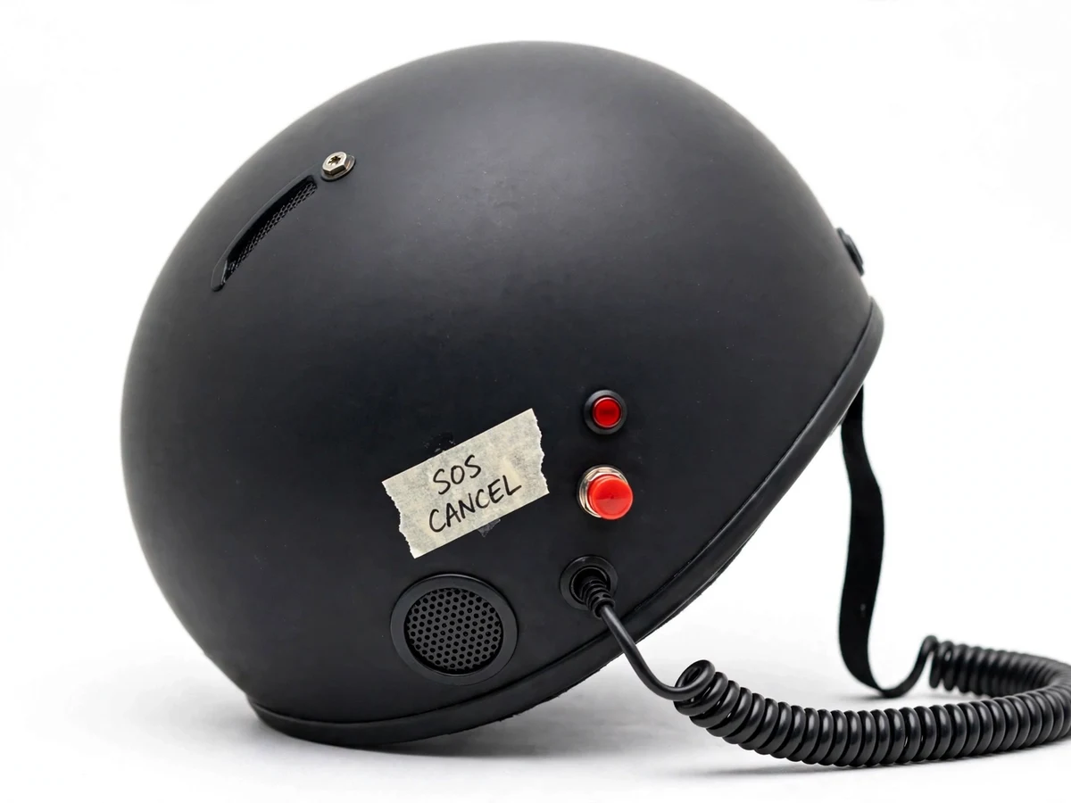
- The buzzer sounds the cancellation countdown; if the rider presses cancel within the window, the event is logged as cancelled.
- If not cancelled, the GPS module's latest fix is read and the GSM module sends the SOS SMS with a map link to each stored emergency number.
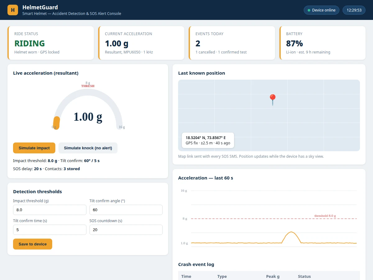
- In parallel, the event (type, time, peak g, location) is published over Wi-Fi to the cloud dashboard, which shows the crash log and last known position.
Tech stack:
- ESP32 development board (Wi-Fi + Bluetooth)
- MPU6050 6-axis inertial sensor (accelerometer + gyroscope)
- NEO-6M GPS module
- SIM800L GSM/GPRS module
- Push-button cancel switch, buzzer, status LEDs
- Cloud dashboard (Firebase/ThingSpeak class) with event log
- Arduino IDE (C/C++ firmware)
- Standard motorcycle helmet shell (retrofitted, non-structural modification)
| Parameter | Value |
|---|---|
| Controller | ESP32 (240 MHz dual-core), Wi-Fi for telemetry |
| Inertial sensor | MPU6050, 6-axis; accelerometer full-scale ±2/±4/±8/±16 g (selectable in firmware) |
| Impact threshold | Configurable in firmware; design tuning range 4–12 g; student sets final value from drop tests |
| GPS | NEO-6M; open-sky accuracy typically ~2.5 m CEP per datasheet (actual fix depends on sky view) |
| Alert channel | SIM800L quad-band GSM; SOS SMS to up to 3 stored contacts with Google Maps link |
| Cancellation | Buzzer countdown, design target 15–30 seconds, cancel push-button |
| Power | Rechargeable Li-ion pack with charging module; design target 8–12 hours of active monitoring per charge (depends on GPS/GSM usage) |
| Dashboard | Live status, crash-event log, last known position panel; offline event buffering on-device |
Project features
- [Crash-signature detection] The MPU6050 measures 3-axis acceleration continuously; firmware flags impact when the resultant acceleration crosses a configured g-threshold, cross-checked against a free-fall-then-shock pattern to reject casual knocks.
- [Fallen-rider tilt check] If the helmet's orientation stays tilted beyond a configured angle for a set confirmation time after a suspected impact, the event is confirmed — reducing false alerts from dropping the helmet while parked.
- [SOS SMS with GPS link] On confirmed impact, the SIM800L texts the stored emergency contacts with a Google Maps link to the GPS fix, so responders get an actionable location, not just a message.
- [Pre-alert cancellation window] A buzzer sounds a configurable countdown (design target 15–30 seconds) before the SOS is sent, letting a conscious rider cancel with a push-button — an honest handling of false positives.
- [Live alert dashboard] The demo dashboard shows ride status, live orientation, the crash-event log with timestamps, and the last known GPS position on a map-style panel.
- [Configurable thresholds] Impact g-threshold, tilt angle, tilt-confirmation time and SOS delay are all firmware constants the student tunes on their own test rig and documents in the report.
- [Offline-first logging] Every event is timestamped on-device even without Wi-Fi and synced to the dashboard when connectivity returns.
What is included
- Working smart-helmet prototype (ESP32, MPU6050, GPS, GSM, buzzer, cancel button fitted into a helmet)
- Complete firmware source code (detection, GPS, SMS, dashboard sync)
- Live alert dashboard setup with event log and position panel
- Circuit and wiring documentation
- Threshold-tuning procedure (buyer-run drop/tilt tests to set impact and tilt values)
- Project report PDF (crash-detection theory, sensor setup, test results from buyer's own trials)
- PPT presentation for final review
- Viva Q&A preparation document (IMU principles, crash signatures, GSM/GPS integration)
- Setup and demonstration guide
Limitations & prerequisites
- The prototype is an academic demonstration of crash-event detection, not a certified safety device; it does not make the helmet crash-worthy — the helmet's own safety certification is what protects the head.
- Impact and tilt thresholds ship as starting values; the student must tune them on their own test rig — final detection behavior depends entirely on their calibration.
- GPS needs an open-sky view and GSM needs mobile signal; underground parking or signal-dead zones prevent fixes and SMS delivery, which the limitations section documents honestly.
- False positives are possible from hard drops (a cancellation window is the mitigation, not a guarantee); the report must present the student's own false-trigger observations.
- The NEO-6M GPS and SIM800L add weight and require the battery pack; continuous GPS-on operation shortens battery life substantially.
Frequently Asked Questions
Which controller is used?
An ESP32. It reads the MPU6050 over I2C, manages the GPS and GSM modules over UART, and publishes events to the cloud dashboard over Wi-Fi.
How does it detect an accident?
The firmware looks for crash signatures: a resultant-acceleration spike above the impact threshold, optionally preceded by free-fall, followed by a prolonged tilted state — then a cancellation countdown before the SOS goes out.
Does it work without mobile signal?
Crash detection and on-device logging work without signal, but the SOS SMS needs GSM coverage and the GPS needs a sky view. The dashboard side works over Wi-Fi independently.
How are false alerts handled?
A buzzer countdown (15–30 seconds, configurable) lets a conscious rider cancel with a push-button. Threshold tuning against real test data is what keeps false alerts low, and that procedure is part of the kit.
Is the helmet still safe to wear?
The electronics are mounted non-structurally inside the liner area without cutting the shell; crash protection remains the helmet's own certification — the device adds alerting, not impact protection.
Is this project suitable for a final-year project?
Yes — for Electronics, IoT and Embedded programs. It combines inertial sensing, embedded firmware, GPS/GSM integration and a cloud dashboard with a genuinely testable detection algorithm. Suitable for B.E./B.Tech final-year projects in Electronics, Electrical, IoT and Embedded Systems.
Components & software requirements
- ESP32 development board (Wi-Fi + Bluetooth)
- MPU6050 6-axis inertial sensor (accelerometer + gyroscope)
- NEO-6M GPS module
- SIM800L GSM/GPRS module
- Push-button cancel switch, buzzer, status LEDs
- Cloud dashboard (Firebase/ThingSpeak class) with event log
- Arduino IDE (C/C++ firmware)
- Standard motorcycle helmet shell (retrofitted, non-structural modification)
Delivery information
Built-to-order project. Delivery timeline is shared after order confirmation based on current queue.
Support terms
Complete documentation, setup guide, and viva preparation included. Support for setup and explanation provided.