
More project photos (2)
The problem
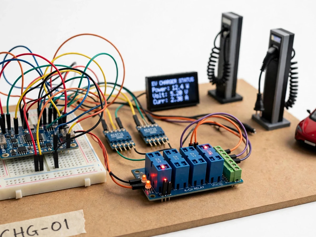
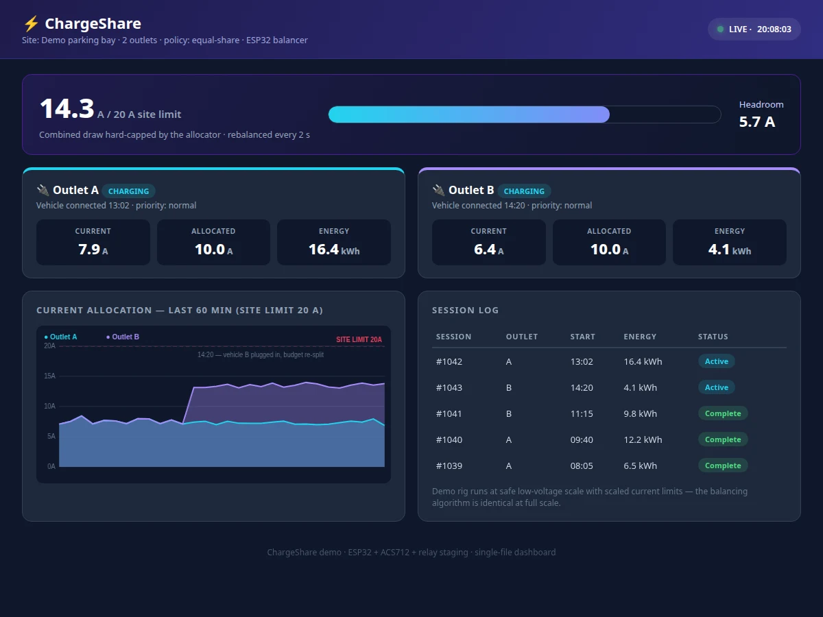
Apartment basements and campuses adding EV chargers hit the same wall: the building's sanctioned load cannot feed every charger at full current simultaneously, and upgrading the sanctioned load is expensive. The industry answer is dynamic load balancing — chargers share a site budget, throttling gracefully instead of tripping the main breaker — but students only ever read about it in application notes. This project builds a working two-outlet balancer around an ESP32: per-outlet current sensors feed a control loop that allocates the site's current budget between outlets, rebalancing within seconds when a vehicle plugs in, finishes, or the site limit changes. A companion dashboard visualizes per-outlet power, the site-limit gauge, the allocation history and a session log. The prototype operates at safe low-voltage demo scale with scaled current limits, which keeps the build student-safe while the algorithm — measurement, allocation policy, rebalancing dynamics — runs exactly as it would at full scale.
How it works
- Each outlet's ACS712 sensor is sampled continuously; the firmware converts readings to RMS current with the student's calibration offset.
- The controller sums both outlets and compares the total against the configured site limit (scaled for the demo rig).
- When headroom exists, outlets run at their requested current; when the sum would exceed the limit, the allocator throttles per the active policy.
- Throttling is applied through relay/contactor staging and PWM pilot control on the demo outlets, re-evaluated every control cycle.
- Plug-in and unplug events are detected from current steps and trigger immediate rebalancing plus a session log entry.
- All readings, allocations and sessions are published over Wi-Fi via MQTT/HTTP; the dashboard renders the live view and the allocation history chart.
Tech stack:
- ESP32 development board (Wi-Fi + ADC)
- ACS712 current sensors (2x, per outlet)
- Relay/contactor staging + PWM pilot control
- 0.96-inch OLED local display
- Low-voltage demo load rig (scaled outlets)
- MQTT/HTTP telemetry to dashboard
- HTML/CSS/JS power dashboard
- Arduino IDE (C/C++ firmware)
| Parameter | Value |
|---|---|
| Outlets | 2 (demo scale) |
| Current sensing | ACS712, approximately ±1.5% typical (datasheet) after offset calibration |
| Demo scale | Low-voltage rig; site limit configurable, scaled to demo currents (design) |
| Control cycle | Re-evaluated every 2 s (configurable in firmware) |
| Rebalance response | Within one control cycle of plug/unplug detection (design target) |
| Telemetry | Wi-Fi MQTT/HTTP to dashboard |
| Dashboard | Single-file web app; gauges, allocation chart, session log |
| Allocation policies | Equal-share and priority-outlet (firmware selectable) |
Project features
- [Per-outlet current sensing] ACS712 Hall-effect sensors measure each outlet's draw continuously, giving the controller the real load picture it allocates against.
- [Dynamic current allocation] The firmware splits the site current budget between active outlets by policy (equal share or priority), rebalancing within seconds of any plug-in, unplug or limit change.
- [Site-limit enforcement] The combined draw is hard-capped at the configured site limit; the controller throttles outlets via relay/PWM control before the limit is breached, never after.
- [Live power dashboard] Per-outlet power cards, a site-limit gauge, an allocation-over-time chart and a session log with energy totals in one view.
- [Session logging] Every charging session records start/end time, energy delivered and peak current, building the usage history the report analyzes.
- [Priority outlet mode] Outlet A can be configured as priority (e.g. an ambulance or staff vehicle), demonstrating policy-based allocation beyond equal sharing.
- [On-device display] A 0.96-inch OLED shows per-outlet current, total load and the active allocation at the charger itself.
What is included
- Working hardware prototype (two-outlet demo rig with sensors, staging relays and controller)
- ESP32 firmware source with sensing, allocation policies and session logging
- Companion dashboard demo (single-file HTML power dashboard)
- ACS712 offset-calibration procedure and record sheet
- Wiring diagram and demo-rig safety notes
- Project report PDF (background, load-balancing principles, allocation algorithms, methodology)
- PPT presentation for final review
- Viva Q&A preparation document (current sensing, control loops, allocation policy, scaling)
Limitations & prerequisites
- The prototype runs at safe low-voltage demo scale — it demonstrates the balancing algorithm, not a mains-voltage charger installation, which needs certified hardware and a licensed electrician.
- ACS712 readings need per-sensor offset calibration by the student; uncalibrated offsets bias every allocation decision.
- The demo uses resistive demo loads, not real EV onboard chargers, so pilot-signal negotiation with actual vehicles is outside the build.
- Relay staging gives stepped throttling, not smooth continuous control; the report discusses this honestly against contactor-based designs.
- Only two outlets are balanced; the allocation logic extends to N outlets in firmware structure, documented as future scope.
- Site-limit changes mid-session are supported in firmware but demonstrated as a configured scenario, not a utility feed.
Frequently Asked Questions
How does the balancer decide who gets how much current?
Each control cycle it totals both outlets' measured draw against the site limit. With headroom, both run free; when the sum would exceed the limit, the active policy (equal-share or priority) assigns each outlet a cap, applied through relay staging and PWM pilot control.
Why build it at low voltage instead of real 230 V?
Safety and demonstrability. The algorithm — measure, allocate, enforce, rebalance — is identical at any scale; running the demo rig at safe low voltage lets the student probe, rewire and demo it freely. A mains version would need certified switchgear, stated as future scope.
What happens when a second vehicle plugs in mid-session?
The current step is detected, a new session starts, and the allocator immediately re-splits the site budget. The dashboard's allocation chart shows the rebalancing moment, which makes an excellent viva demo.
How accurate is the current sensing?
The ACS712 is approximately ±1.5% typical per its datasheet after the student's offset calibration. The report documents the calibration procedure and treats residual error as a design input, not a hidden flaw.
What is priority mode for?
Outlet A can be marked priority (think staff or emergency vehicle): under contention it keeps its full request while outlet B absorbs the throttling. It demonstrates that allocation is policy, not just arithmetic.
Is this project suitable for a final-year project?
Yes — for Electronics, Electrical, IoT and Embedded Systems programs. It combines power sensing, real-time control, policy design and a live dashboard around a genuinely current industry problem. Suitable for B.E./B.Tech final-year projects in Electronics, Electrical, IoT and Embedded Systems.
Components & software requirements
- ESP32 development board (Wi-Fi + ADC)
- ACS712 current sensors (2x, per outlet)
- Relay/contactor staging + PWM pilot control
- 0.96-inch OLED local display
- Low-voltage demo load rig (scaled outlets)
- MQTT/HTTP telemetry to dashboard
- HTML/CSS/JS power dashboard
- Arduino IDE (C/C++ firmware)
Delivery information
Built-to-order project. Delivery timeline is shared after order confirmation based on current queue.
Support terms
Complete documentation, setup guide, and viva preparation included. Support for setup and explanation provided.