
More project photos (2)
The problem
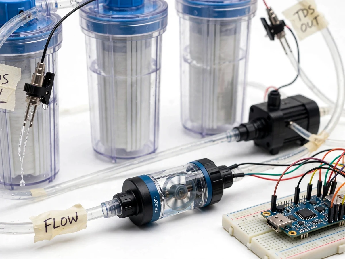
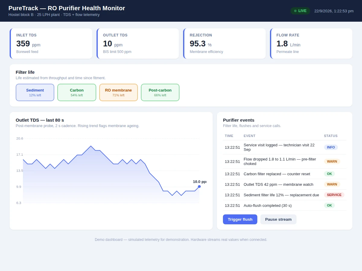
RO purifiers fail quietly: the membrane ages, rejection slides from 95% toward 80%, and the family keeps drinking the water because nobody measures it. Service visits happen on calendar time, not on condition. The engineering gap is continuous health monitoring — TDS in versus TDS out, flow rate, and filter life counted from actual throughput — with the controller itself running flush cycles and raising service tickets before the water quality slips. This project builds that on an ESP32: two TDS probes straddle the membrane, a flow sensor meters the permeate line, the firmware computes rejection percentage and remaining filter life, and a dashboard shows the health picture with alerts a hostel warden or facility manager can act on.
How it works
- Feed water passes the inlet TDS probe, then the pre-filters, pump and RO membrane, then the outlet TDS probe.
- The ESP32 reads both probes and the flow sensor continuously, converting raw ADC values with the calibration constants.
- Firmware computes rejection percentage and updates remaining life for each filter stage from throughput.
- On schedule, the controller opens the flush solenoid for a timed flush and logs the event.
- All readings stream to the dashboard; if outlet TDS or rejection crosses its limit, a service alert is raised.
- When a filter is replaced, its life counter resets from the dashboard with the fitment date logged.
Tech stack:
- ESP32 development board (Wi-Fi telemetry)
- 2x TDS (total dissolved solids) sensor probes
- YF-S201 hall-effect flow sensor
- Solenoid valve (flush control) + relay
- Small RO filter housings + pump (demo rig)
- Single-page service dashboard (HTML/JS)
- Arduino IDE (C/C++ firmware)
| Parameter | Value |
|---|---|
| Controller | ESP32, Wi-Fi dashboard sync |
| TDS probes | 2x analog TDS probes (inlet + outlet); calibrated against reference solution at build |
| Flow sensor | YF-S201; approximately 1–30 L/min range per typical specs |
| Rejection | Computed (TDSin − TDSout) / TDSin; healthy membrane typically 90%+ (design target) |
| Flush | Solenoid valve, timed auto-flush (configurable interval) |
| Filter stages | Sediment, carbon, RO membrane, post-carbon — life tracked per stage |
| Dashboard | TDS curves, rejection trend, filter-life bars, alert feed |
| Demo rig | Bench-scale housings + pump; not a certified drinking-water appliance |
Project features
- [Dual TDS measurement] Probes on the feed and permeate lines give inlet and outlet TDS, so membrane performance is measured, not assumed.
- [Rejection percentage] Firmware computes salt rejection from the two readings — the single number that says whether the membrane is healthy.
- [Flow monitoring] A hall-effect flow sensor tracks permeate flow; falling flow flags choked pre-filters before the user notices weak output.
- [Filter-life tracking] Each stage's remaining life is counted from throughput and time since fitment, with replacement alerts per stage.
- [Auto-flush control] The controller runs timed membrane flush cycles through a solenoid valve to extend membrane life.
- [Service dashboard] Inlet/outlet TDS curves, rejection trend, filter-life bars and an alert feed give the full maintenance picture.
- [Calibration procedure] TDS probes are calibrated against a reference solution during the buyer's build and the procedure is documented.
What is included
- Working purifier-monitor prototype (dual TDS probes, flow sensor, flush valve, ESP32)
- Bench RO demo rig (housings, pump, tubing)
- Complete firmware source code (sensing, rejection math, filter-life, flush, dashboard sync)
- Service dashboard with curves and maintenance alerts
- Circuit and wiring documentation
- TDS calibration procedure (buyer-run, with reference solution steps)
- Project report PDF (RO principles, instrumentation, calibration data from the buyer's run)
- PPT presentation for final review
- Viva Q&A preparation document (TDS, RO membranes, rejection, sensor calibration)
Limitations & prerequisites
- A bench demonstration rig, not a certified drinking-water appliance — no claim is made about producing safe drinking water.
- TDS is an indicative parameter; it does not detect pathogens, and the project makes no health or purity certification claims.
- Probe accuracy depends on the buyer's calibration run; uncalibrated readings are indicative only.
- Filter-life estimates are design targets from throughput models, not manufacturer ratings.
- The demo uses clean tap/borewell-type water; heavily contaminated feeds are out of scope.
Frequently Asked Questions
What does the rejection percentage tell me?
It is (inlet TDS − outlet TDS) / inlet TDS — the fraction of dissolved solids the membrane removes. A healthy membrane holds 90%+, and a falling trend is the earliest sign of ageing.
Why two TDS probes?
One probe only tells you the output number. Inlet plus outlet lets the firmware compute rejection, which is the real health signal — output TDS alone moves with the feed water too.
How does it know a filter needs replacing?
Each stage's life is counted from actual throughput and days since fitment; the dashboard shows remaining-life bars and raises an alert per stage.
What does the auto-flush do?
The controller periodically opens a flush solenoid to sweep concentrate off the membrane surface, which extends membrane life in normal service.
Is the output water certified safe?
No — this is an instrumentation project on a bench rig, not a certified appliance. It measures and reports; it makes no drinking-water safety claims.
Is this project suitable for a final-year project?
Yes — for Electronics, Electrical and IoT & Embedded programs. It combines chemical sensing, flow measurement, control and a maintenance dashboard in one working system. Suitable for B.E./B.Tech final-year projects in Electronics, Electrical and IoT & Embedded Systems.
Components & software requirements
- ESP32 development board (Wi-Fi telemetry)
- 2x TDS (total dissolved solids) sensor probes
- YF-S201 hall-effect flow sensor
- Solenoid valve (flush control) + relay
- Small RO filter housings + pump (demo rig)
- Single-page service dashboard (HTML/JS)
- Arduino IDE (C/C++ firmware)
Delivery information
Built-to-order project. Delivery timeline is shared after order confirmation based on current queue.
Support terms
Complete documentation, setup guide, and viva preparation included. Support for setup and explanation provided.