
More project photos (2)
The problem
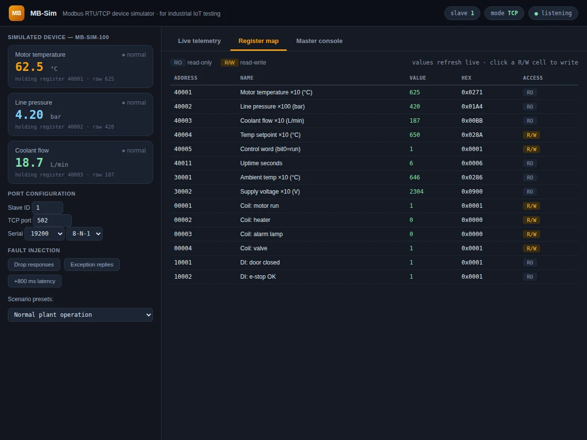
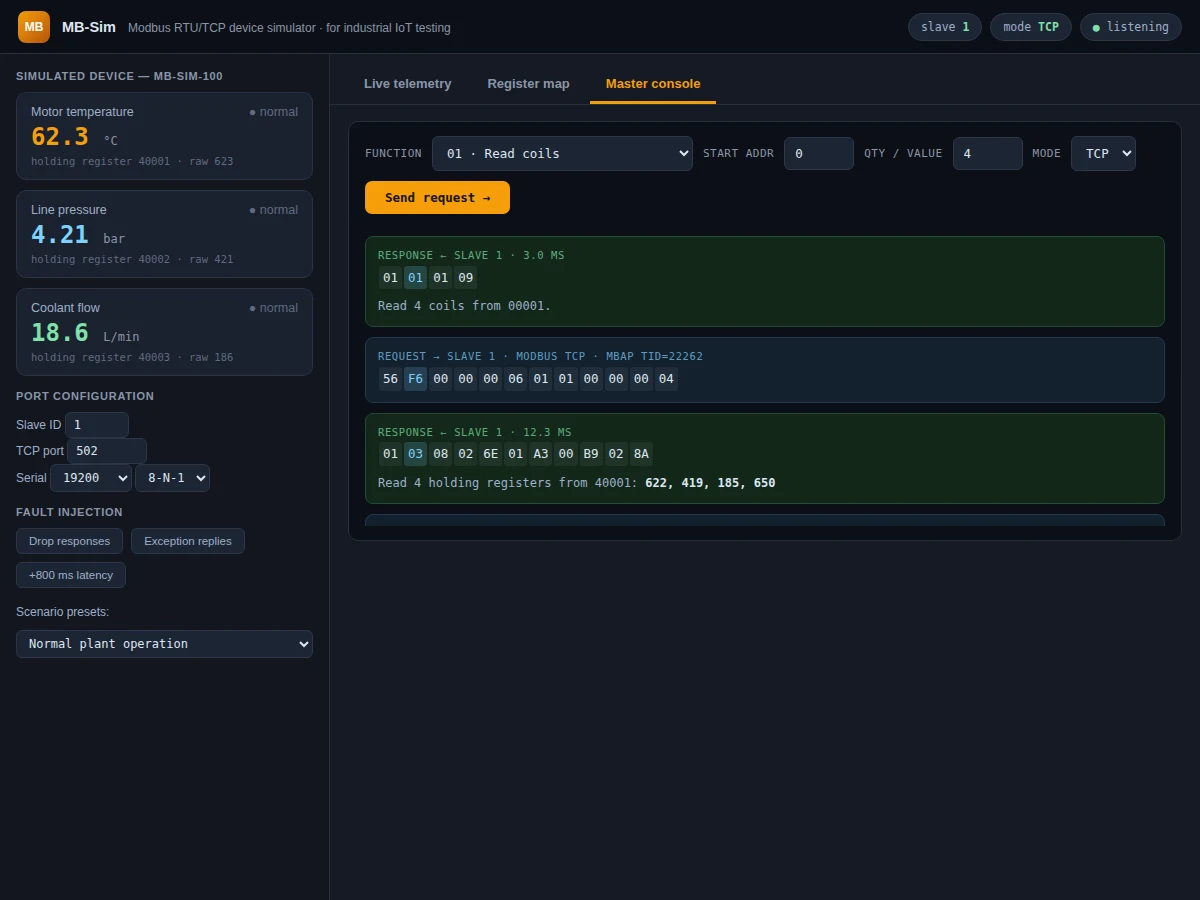
Testing an industrial IoT gateway against real Modbus hardware is slow and expensive: you need the PLC or sensor, the wiring, and you cannot easily make it fail on demand to check your error handling. A simulator solves this — a virtual Modbus slave that answers requests exactly like the real device, with telemetry you can drive into alarm states and faults you can inject at will. This project builds that simulator as an interactive tool. A device model generates realistic telemetry (motor temperature with thermal drift, line pressure, coolant flow) and maps it to holding registers, input registers, coils and discrete inputs per the Modbus data model. The register map panel shows every address live with read/write access flags, the master console lets you compose requests (function codes 01/02/03/04/05/06/16 over RTU or TCP), and every frame renders as hex bytes with the CRC-16 highlighted and a decoded explanation. Scenario presets (overheating motor, pressure spike, flaky comms) plus fault injection (dropped responses, exception replies, added latency) make failure testing one click away.
How it works
- The simulator runs a device model: temperature, pressure and flow update every 400 ms from drift-plus-noise dynamics toward scenario-dependent targets.
- Each telemetry value is scaled into its Modbus register (e.g. temperature ×10 into holding register 40001); coils reflect digital outputs like motor run and alarm.
- The master console builds a request PDU for the chosen function code, wraps it in RTU framing (slave ID + CRC-16) or a TCP MBAP header.
- The virtual slave parses the frame, validates the CRC, executes the read/write against the device model, and builds the response frame.
- Both frames render in the console as annotated hex with timing, and the decoded result explains registers read or values written.
- Fault injection hooks sit in the response path: dropped replies produce client-side timeouts, exception mode returns Modbus exception codes.
- Scenario presets retarget the telemetry dynamics — e.g. overheating ramps temperature past the alarm threshold, which flips the alarm coil.
Tech stack:
- JavaScript (ES6) · HTML5 canvas charts
- Modbus RTU/TCP framing (implemented)
- CRC-16/Modbus algorithm
- Device physics model
- Single-file web app, zero dependencies
- Git
| Parameter | Value |
|---|---|
| Protocol | Modbus RTU + Modbus TCP (design target) |
| Function codes | 01, 02, 03, 04, 05, 06, 16 (design target) |
| Slave addressing | 1–247 configurable (design target) |
| CRC | CRC-16/Modbus, poly 0xA001 (design target) |
| Telemetry tick | 400 ms model update (design target) |
| Registers | 6 holding + 2 input + 4 coils + 2 DI in map (design target) |
| Faults | Drop, exception, latency injection (design target) |
Project features
- [Live telemetry engine] Motor temperature, line pressure and coolant flow evolve with a physics-style model (thermal drift, noise) and map to registers in real time.
- [Full register map] Holding registers, input registers, coils and discrete inputs with Modbus address notation, live values, hex view and R/W access flags.
- [Master console] Compose requests with any function code (01/02/03/04/05/06/16), start address and quantity over Modbus RTU or TCP and send them to the simulated slave.
- [Frame inspector] Every request and response renders as hex bytes with the function code and CRC-16 highlighted, plus a plain-English decode of what happened.
- [Fault injection] Drop responses, force exception replies or add latency to test how your gateway/client handles timeouts and errors.
- [Scenario presets] One-click scenarios: normal operation, overheating motor, pressure spike, flaky comms.
- [Writable registers] Click any R/W register or coil to write it — setpoints and control bits respond immediately in the telemetry.
- [Live trend chart] Temperature, pressure and flow charted together over a rolling 48-second window.
What is included
- Complete single-file Modbus simulator application
- Modbus protocol documentation (framing, function codes, CRC, data model)
- Scenario and fault-injection guide for gateway testing
- Project report PDF (background, Modbus theory, simulator design, test procedure)
- PPT presentation for final review
- Viva Q&A preparation document (Modbus vs MQTT, RTU vs TCP, CRC, registers/coils)
Limitations & prerequisites
- The simulator speaks correct Modbus framing but runs in the browser — it does not open real serial ports or TCP sockets; hardware integration is documented as the extension path.
- Telemetry is a simplified drift/noise model, not a calibrated process simulation — it is designed for protocol and error-handling tests.
- Timing figures are expected client-side latencies, not measured on real serial hardware.
- Only the listed function codes are implemented; diagnostics (08) and FIFO (24) are out of scope.
Frequently Asked Questions
What is Modbus and why simulate it?
Modbus is the dominant serial/IP protocol in industrial automation. Simulating a slave lets you develop and test IoT gateways, SCADA clients and dashboards without physical hardware — and lets you inject failures hardware never would on demand.
Does it do real Modbus frames?
Yes — requests and responses are built byte-by-byte with correct function codes, addressing and CRC-16 (RTU) or MBAP headers (TCP), and the console shows every byte.
How do I test my own gateway code against it?
Use the documented register map and frame format as the reference: point your client at the same addresses and function codes, and compare its parses against the console's decoded frames.
What faults can I inject?
Dropped responses (client timeouts), exception replies (illegal address), added latency, plus scenario presets like overheating and pressure spikes that drive coils into alarm states.
RTU or TCP — which should I learn first?
The console supports both; RTU teaches framing and CRC on a byte stream, TCP teaches the MBAP header. The report compares them directly.
Is this project suitable for a final-year project?
Yes — for IoT & Embedded, Electronics and Electrical programs. It demonstrates industrial protocols, binary framing, simulation and test engineering. Suitable for B.E./B.Tech final-year projects in IoT & Embedded, Electronics and Electrical.
Components & software requirements
- JavaScript (ES6) · HTML5 canvas charts
- Modbus RTU/TCP framing (implemented)
- CRC-16/Modbus algorithm
- Device physics model
- Single-file web app, zero dependencies
- Git
Delivery information
Built-to-order project. Delivery timeline is shared after order confirmation based on current queue.
Support terms
Complete documentation, setup guide, and viva preparation included. Support for setup and explanation provided.