
More project photos (2)

The problem
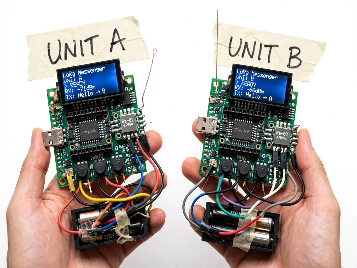
When the network goes down — in a disaster zone, on a trek, across a large farm — ordinary messaging dies with it. LoRa exists precisely for that gap: chirp spread-spectrum modulation that trades data rate for kilometres of range at milliwatts of power. This project turns that principle into something you can hold: two identical handheld messenger units, each built around an ATmega328P with a Ra-02 433 MHz LoRa module, an OLED display, three message buttons and an AA battery pack. Compose a short text on Unit A, and it appears on Unit B's screen with the received signal strength beside it. The build covers the full peer-to-peer loop — addressing so each unit knows who a message is for, acknowledgements, RSSI-based link quality, and the low-power behavior that lets such units run for days on batteries.
How it works
- The user composes a message on Unit A using the buttons — scrolling presets or entering characters — and presses send.
- The ATmega328P frames the text with the destination address and a sequence number, and hands it to the Ra-02 LoRa module.
- The module transmits using chirp spread-spectrum modulation at 433 MHz, which resists interference and reaches far at low power.
- Unit B's Ra-02 receives the chirps, decodes them, checks the address, and passes the payload to its microcontroller.
- Unit B displays the message with its measured RSSI and transmits a short acknowledgement back to Unit A.
- Unit A marks the message delivered on its OLED; if no acknowledgement arrives, it reports the failure honestly instead of pretending.
- Between activity both units sleep to conserve the AA batteries, waking on button press or incoming preamble.
Tech stack:
- ATmega328P microcontroller (Arduino-compatible)
- Ra-02 LoRa module (SX1278, 433 MHz)
- OLED character/graphic display
- Push-button input interface
- AA battery power with sleep modes
- C/C++ firmware (Arduino IDE)
| Parameter | Value |
|---|---|
| Radio | Ra-02 LoRa, 433 MHz ISM band |
| Modulation | Chirp spread spectrum (LoRa) |
| Receiver sensitivity | Down to approximately −148 dBm (SX1278 datasheet) |
| Range | Kilometre-scale line-of-sight (design target; buyer-measured on site) |
| Display | OLED with message thread and RSSI readout |
| Input | 3 push buttons (presets + character entry) |
| Power | AA battery pack per unit, sleep between activity (expected) |
| Units supplied | 2 (Unit A and Unit B, addressed pair) |
Project features
- [Peer-to-peer LoRa texting] Two identical units exchange addressed text messages directly over the 433 MHz LoRa link, with no gateway or network.
- [OLED chat display] Each unit shows the conversation with unit identity, message direction and status on a crisp OLED.
- [Live RSSI readout] Every received message displays its signal strength (e.g. −71 dBm), turning link quality into a visible, measurable quantity.
- [Button text entry] Three push buttons drive a message composer with preset phrases and character entry, designed for gloved or field use.
- [Addressing and acknowledgements] Unit A / Unit B addressing with delivery acknowledgement, demonstrating reliable transfer over an unreliable medium.
- [Battery operation] AA battery packs with low-power sleep between activity, showing the energy profile that makes LoRa field devices practical.
- [Range-test procedure] A buyer-run procedure for measuring usable range and RSSI fall-off across the student's own test sites.
What is included
- Two complete handheld messenger units (PCB, ATmega328P, Ra-02, OLED, buttons, battery pack)
- Peer-to-peer messaging firmware with full source
- Range and RSSI measurement procedure (buyer-run)
- Battery-life estimation worksheet
- Project report PDF (LoRa theory, spread spectrum, link budget, measurements)
- PPT presentation for final review
- Viva Q&A preparation document (chirp modulation, spreading factor, RSSI, addressing)
Limitations & prerequisites
- Text only, at low data rates — LoRa trades throughput for range; no images, voice or fast chat.
- Real-world range is environment-dependent (buildings, terrain, antenna orientation) and is measured by the student, never pre-claimed.
- Button text entry is deliberately simple and slower than a phone keyboard — a field-device trade-off, stated honestly.
- The 433 MHz band has regional duty-cycle and power rules; the firmware keeps transmissions short and the report notes the regulatory position.
- Acknowledgements confirm delivery between the two units only; there is no store-and-forward for out-of-range units.
Frequently Asked Questions
How far can the two units really talk?
That depends on terrain, antenna orientation and spreading-factor settings — kilometres are achievable line-of-sight, far less through buildings. The included procedure has the student measure their own range and RSSI fall-off at several sites and report those real numbers.
Why LoRa instead of Wi-Fi or Bluetooth?
Wi-Fi and Bluetooth reach tens of metres; LoRa's chirp spread spectrum reaches kilometres at similar or lower power. The trade-off is data rate — perfect for short text, wrong for video — and the project makes that trade-off tangible.
What does the RSSI number on the screen mean?
Received Signal Strength Indicator, in dBm — how loud the other unit sounds. Values nearer zero are stronger; the units typically show around −60 to −90 dBm at classroom distances, and the number visibly drops as the units separate.
How do you type with only three buttons?
The composer offers scrollable preset phrases for fast field use plus a character-entry mode. It is slower than a touchscreen by design — the project is about the radio link, and the UI honesty is part of the report.
Does it need any network or SIM card?
No. The two units talk directly to each other, peer to peer. That is the entire point: messaging that works where there is no infrastructure at all.
Is this project suitable for a final-year project?
Yes — for Electronics, Communication and IoT programs. It demonstrates long-range wireless communication end to end: modulation, addressing, acknowledgements, link-quality measurement and low-power design. Suitable for B.E./B.Tech final-year projects in Electronics, Communication and IoT.
Components & software requirements
- ATmega328P microcontroller (Arduino-compatible)
- Ra-02 LoRa module (SX1278, 433 MHz)
- OLED character/graphic display
- Push-button input interface
- AA battery power with sleep modes
- C/C++ firmware (Arduino IDE)
Delivery information
Built-to-order project. Delivery timeline is shared after order confirmation based on current queue.
Support terms
Complete documentation, setup guide, and viva preparation included. Support for setup and explanation provided.