
More project photos (2)
The problem
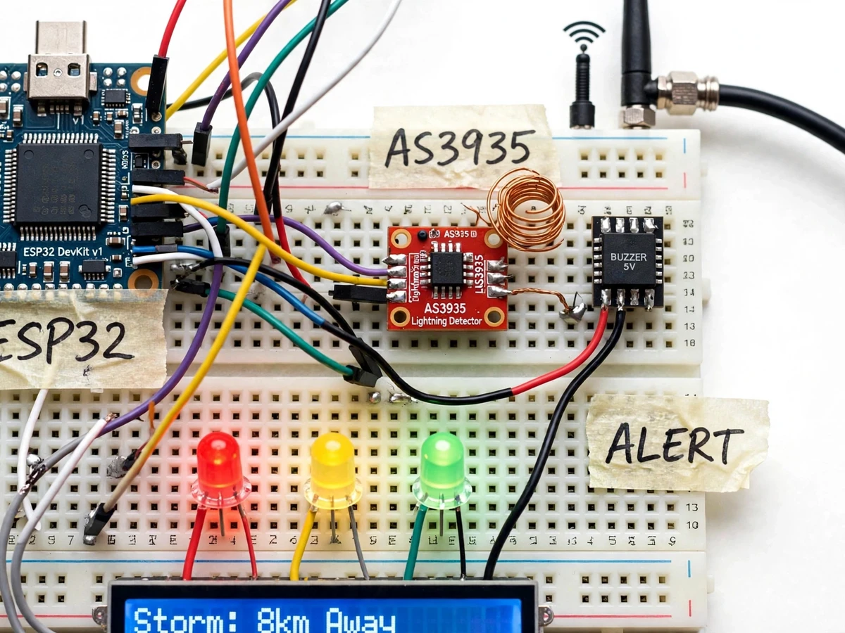
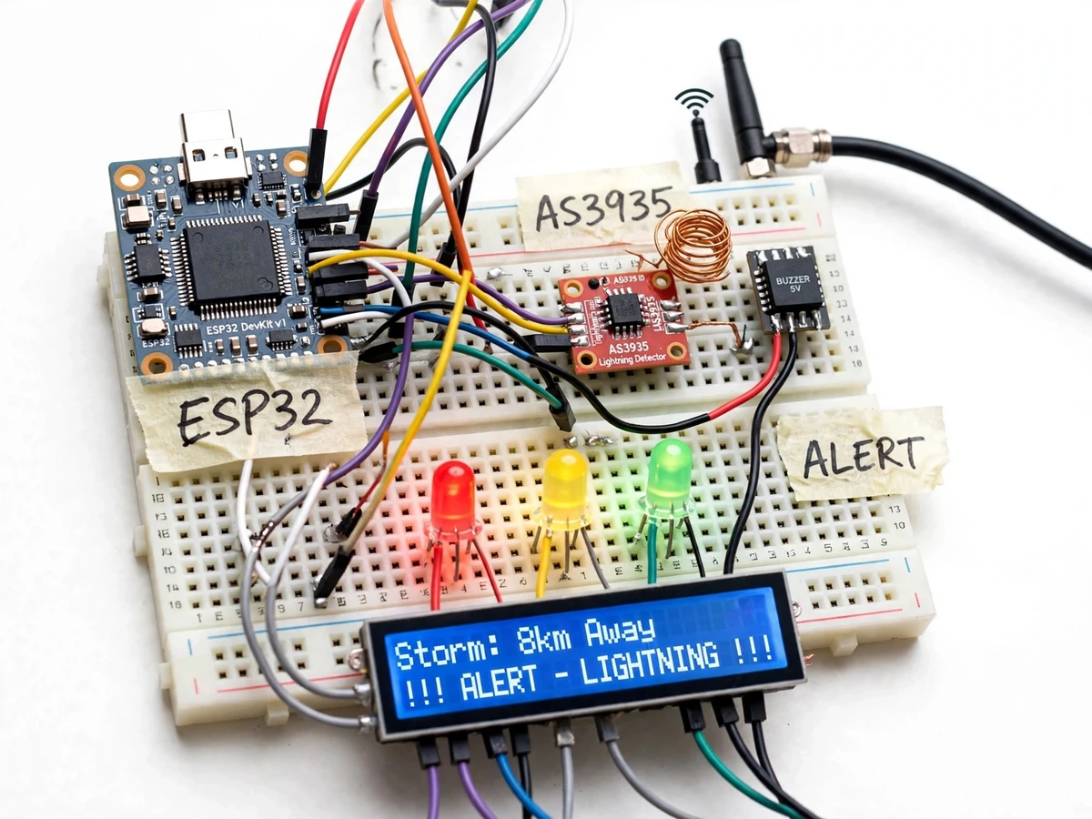
Lightning kills and starts fires, and the most useful warning is simply knowing a storm is approaching while it is still kilometres away. The AS3935 is a remarkable little chip: a tuned lightning detector that listens for the specific electromagnetic signature of a strike, rejects man-made noise, and estimates the distance to the storm front in kilometres. This project puts it on a student-built prototype with an ESP32: the sensor's strike and distance data drive a three-LED distance display (near, approaching, distant), a buzzer for close strikes, and a 20x4 LCD that announces the storm distance plainly. The report is honest about the physics — the distance is a statistical estimate, not a measurement, and the system complements rather than replaces official weather warnings — which makes for a stronger viva than an overclaimed gadget.
How it works
- The AS3935 with its tuned coil antenna continuously listens for lightning electromagnetic signatures via SPI to the ESP32.
- On a validated strike event, the chip reports the strike energy and its statistical distance estimate to the storm front.
- Firmware maps the distance into three bands: distant (green LED), approaching (yellow LED), near (red LED + buzzer).
- The LCD updates with the storm distance and alert text each time a strike is registered.
- The AS3935's disturber-rejection registers are configured per the tuning guide to suppress man-made switching noise.
- An external whip antenna extends reception range; the tuning procedure verifies the resonant setup on the student's build.
Tech stack:
- ESP32 DevKit v1 (Arduino/C++ firmware)
- AS3935 lightning detector module (SPI)
- Tuned coil antenna + whip antenna
- 5 V buzzer module
- Red/yellow/green indicator LEDs
- 20x4 character LCD
| Parameter | Value |
|---|---|
| Controller | ESP32 DevKit v1 (design) |
| Sensor | AS3935 Franklin lightning detector, SPI (design) |
| Detection range | Up to ~40 km front detection, statistical estimate (datasheet) |
| Distance resolution | 1 km steps per AS3935 algorithm (datasheet) |
| Alerts | 3 LED bands + 5 V buzzer, configurable thresholds (design) |
| Display | 20x4 character LCD (design) |
| Supply | 5 V DC regulated (expected) |
Project features
- [AS3935 lightning sensing] A dedicated lightning-detector chip with a tuned coil antenna captures strike electromagnetic pulses and reports strike energy and estimated distance.
- [Storm distance estimation] The sensor's front-distance algorithm reports the storm front in kilometres, shown live on the LCD.
- [Three-band LED alert] Red, yellow and green LEDs map to near, approaching and distant storm bands for at-a-glance awareness.
- [Buzzer alert] A 5 V buzzer sounds on close strikes, with the alert threshold configurable in firmware.
- [Live LCD storm display] The 20x4 LCD announces storm distance and alert state in plain language.
- [Disturber rejection] The AS3935's man-made noise rejection is configured and documented, with the report explaining false-positive sources honestly.
- [Antenna setup guide] Coil-antenna tuning and placement guidance so the student's build actually receives strikes instead of noise.
What is included
- Working detector prototype (ESP32, AS3935 module, antennas, buzzer, LEDs, 20x4 LCD)
- Arduino firmware with distance bands and alert logic
- Antenna tuning and placement guide
- Wiring diagram and connection list
- Disturber-rejection configuration notes
- Project report PDF, PPT presentation and viva Q&A document
Limitations & prerequisites
- Storm distance is a statistical estimate from strike energy, not a measurement — the report explains the algorithm's limits openly.
- The detector needs real storms to demonstrate fully; the report includes a buzzer/LED self-test mode and a simulated-strike test procedure for dry-season demos.
- Man-made electrical noise can cause false positives despite disturber rejection; antenna placement per the guide matters.
- This is an educational alert aid, NOT a substitute for official meteorological warnings or a certified lightning-safety system.
- Indoor operation attenuates reception; the guide covers outdoor placement for best results.
Frequently Asked Questions
How does it detect lightning without seeing it?
Lightning emits a powerful electromagnetic pulse. The AS3935 is a tuned receiver that recognises the pulse signature, measures its energy, and converts that into a statistical distance estimate — the same principle used in consumer weather stations.
How accurate is the distance?
It is an estimate in 1 km steps, good enough to tell 'storm approaching' from 'storm overhead', but not a precision measurement. The report explains the estimation openly — an honest viva answer beats a claimed accuracy.
What if there are no storms during my demo?
The firmware includes a self-test mode that exercises the buzzer, LEDs and LCD, plus a simulated-strike procedure so the full alert chain is demonstrable in any season. The report documents both.
Will it false-trigger on electrical noise?
It can — switching transients resemble strikes to any RF receiver. The AS3935's disturber-rejection registers are configured to suppress this, and the antenna placement guide minimises indoor noise pickup. The report discusses this as a real engineering trade-off.
Can it warn before the storm arrives?
That is the entire point: the chip detects fronts up to about 40 km away, so the first alerts typically come well before the storm is overhead — while remaining an aid, not a certified warning system.
Is this project suitable for a final-year project?
Yes — for Electronics and IoT & Embedded programs. It demonstrates RF sensing, SPI interfacing, statistical estimation, alert logic and unusually honest treatment of sensor limits. Suitable for B.E./B.Tech final-year projects in Electronics and IoT & Embedded.
Components & software requirements
- ESP32 DevKit v1 (Arduino/C++ firmware)
- AS3935 lightning detector module (SPI)
- Tuned coil antenna + whip antenna
- 5 V buzzer module
- Red/yellow/green indicator LEDs
- 20x4 character LCD
Delivery information
Built-to-order project. Delivery timeline is shared after order confirmation based on current queue.
Support terms
Complete documentation, setup guide, and viva preparation included. Support for setup and explanation provided.