
More project photos (2)
The problem
Radio-frequency wireless dominates short-range communication, but the RF spectrum is crowded, license-regulated, and unusable where radio interference is a hazard — hospitals, aircraft cabins, and certain industrial plants. Students studying communication theory rarely see modulation outside a textbook equation; amplitude modulation, link budgets, and ambient-noise rejection stay abstract. Optical wireless communication, popularly called Li-Fi, offers a tangible alternative: visible light carries information, is immune to RF interference, and cannot pass through walls, which confines the signal to the room it is meant for. A bench-top audio link makes these ideas concrete — students watch a flicker-free LED carry music, measure how range and sunlight degrade the signal, and characterize a real channel end to end. That visibility is what classroom RF modules seldom provide, and it is why an audio-over-light prototype remains a worthwhile electronics build.
How it works
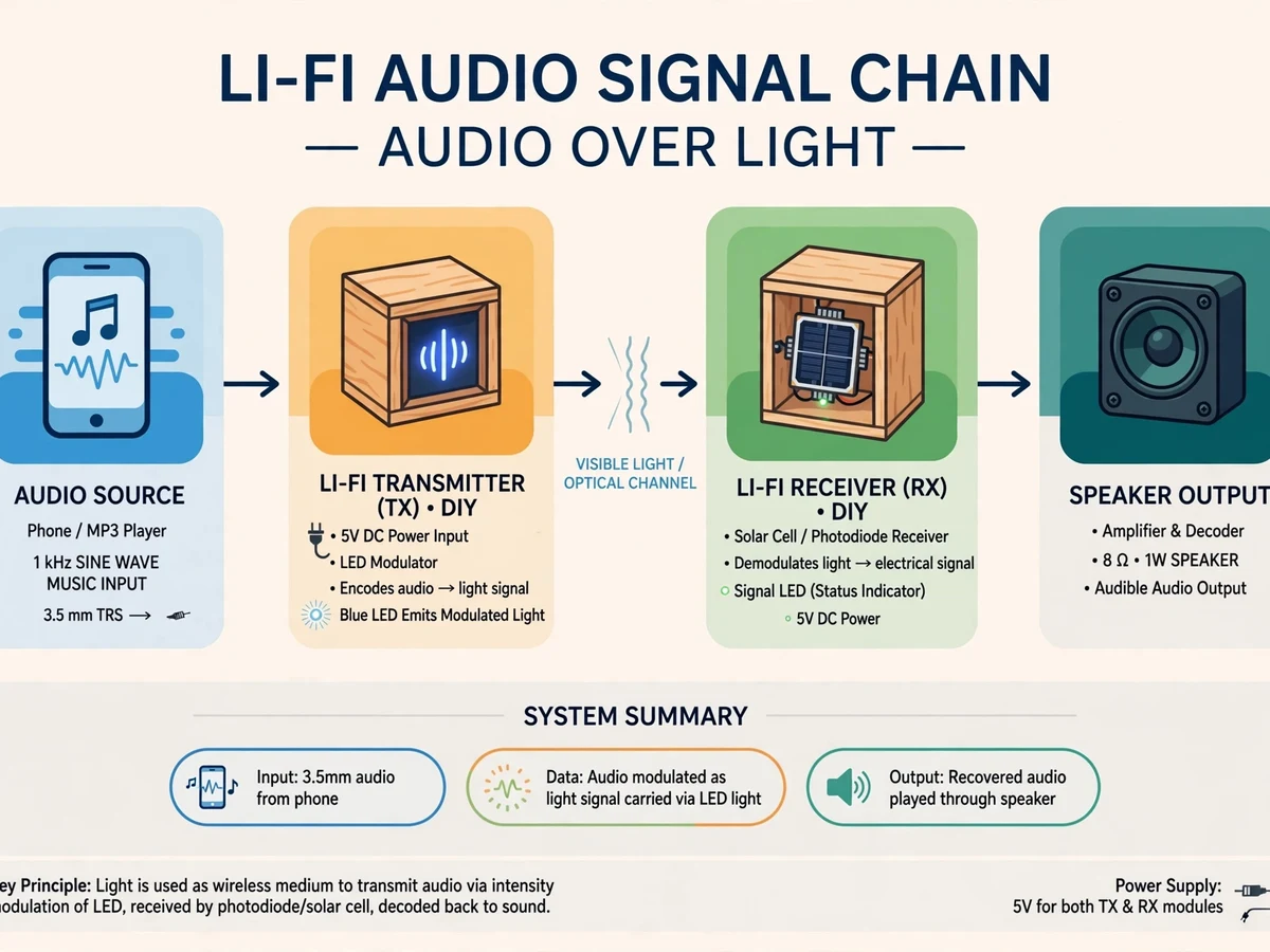
- An audio source (phone/laptop AUX output) feeds the transmitter's op-amp pre-amplifier stage.
- The audio modulates the MOSFET constant-current LED driver, so the LED's intensity varies with the instantaneous audio voltage (amplitude modulation of light).
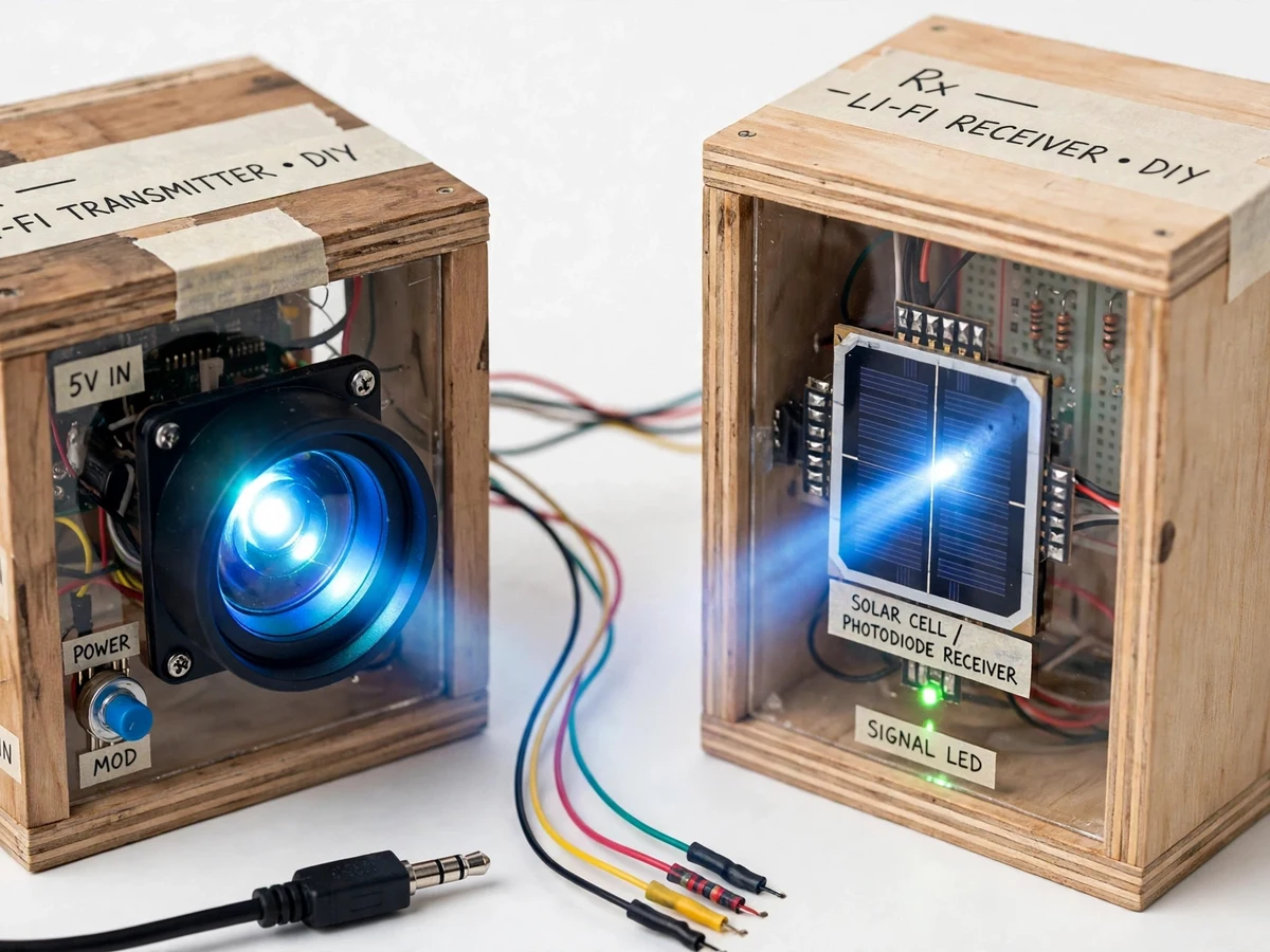
- The modulated beam travels through free space; the modulation runs far above visible flicker frequency, so the LED appears to glow steadily.
- At the receiver, a solar cell (large-area, simple) or BPW34 photodiode (fast, sensitive) converts the varying light back into a varying photocurrent.
- A transimpedance amplifier (op-amp stage) converts the photocurrent into a clean voltage signal.
- Filtering removes DC bias and ambient-light drift; the audio power amplifier stage then boosts the signal.
- The amplified signal drives the speaker, reproducing the original audio live, with oscilloscope test points available for waveform checks.
Project features
- Real-time audio transmission through modulated visible light — no RF at all
- High-brightness LED transmitter with MOSFET-based constant-current driver
- Dual receiver options: solar-cell receiver and faster photodiode receiver
- Op-amp transimpedance amplifier plus filter stage on the receiver side
- LM386 / TDA2050-class audio power amplifier driving a speaker
- Volume and gain control stages on both transmitter and receiver
- Works with any audio source: phone, laptop or MP3 player via AUX input
- Range testing rig: procedure for measuring audio quality vs transmitter–receiver distance
- Ambient-light interference tests (indoor light vs direct sunlight), test procedure documented
- Complete circuit documentation: schematic, component list and test-point voltages
What is included
- Working Li-Fi transmitter + receiver prototype with speaker output
- Complete circuit schematics and wiring diagrams
- Component list with ratings and test-point voltage tables
- Range and ambient-light measurement tables for the report
- Project report PDF (theory, circuit design, test results, conclusion)
- PPT presentation
- Viva Q&A preparation document (modulation theory, photodiode vs solar cell, Li-Fi vs Wi-Fi)
FAQs
- What is Li-Fi and how does it differ from Wi-Fi? Li-Fi transmits data using visible light instead of radio waves. It needs line of sight, is immune to RF interference, and cannot pass through walls — a confinement that is also a security property. This build demonstrates the core principle: modulating light intensity to carry information.
- What range does the prototype achieve? About 1–3 metres indoors (typical; range-test procedure in the report); the report documents the procedure for measuring audio quality against transmitter–receiver distance.
- Does it need darkness to work? No. Normal indoor lighting is fine; only direct sunlight on the receiver causes noticeable interference, and the filter stage rejects most of it. The ambient-light test procedure is documented in the report.
- Can it carry music, or only speech? Both — the analog path covers roughly 300 Hz to 8 kHz, so speech and music reproduce clearly. Fidelity is limited by the analog chain: fine for voice and casual listening, not hi-fi.
- Why does the LED look steady while carrying audio? The modulation runs far above the frequency the human eye can perceive, so the brightness variations that encode the audio are invisible — the LED appears to glow constantly.
- Why build both a solar-cell and a photodiode receiver? It is a deliberate trade-off study: the solar cell is large-area and simple to interface, while the BPW34 photodiode is faster and more sensitive. The report includes the procedure for comparing their performance.
Limitations & prerequisites
- Strictly line-of-sight: any obstruction between LED and receiver breaks the link.
- Strong ambient light (direct sunlight) degrades the signal; indoor demonstration is recommended.
- Range is limited to a few metres on this prototype; it is a proof-of-concept, not a networking product.
- Audio fidelity is limited by the analog chain — good for voice and casual music, not hi-fi.
Components & software requirements
- High-brightness white LED + MOSFET constant-current LED driver
- Audio pre-amplifier and modulator stage (op-amp based)
- Solar cell panel / BPW34 photodiode receiver
- Op-amp transimpedance amplifier + filter stage
- LM386 / TDA2050-class audio power amplifier + speaker
- AUX input interface, regulated 9–12 V DC power supply
Specifications
| Parameter | Value |
|---|---|
| Communication medium | Visible light (optical wireless, Li-Fi principle) |
| Modulation scheme | Amplitude modulation of LED intensity by audio signal |
| Transmitter | High-brightness LED, MOSFET constant-current driver |
| Receiver options | Solar cell panel (simple) / photodiode + TIA (sensitive) |
| Usable range | ~1–3 m indoors (measured and tabulated in the report) |
| Audio bandwidth | ~300 Hz – 8 kHz voice/music range on the prototype |
| Latency | Effectively zero (analog path, no digitization delay) |
| Line of sight | Required — optical path must be unobstructed |
| Power supply | Regulated 9–12 V DC for transmitter and receiver |
| Output | Speaker playback + oscilloscope test points for waveforms |