
More project photos (2)

The problem
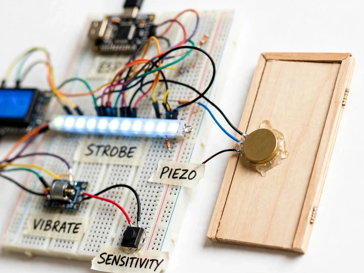
A knock on the door is an audio event — useless to someone who cannot hear it. Hearing-impaired people miss visitors, deliveries and neighbours because the entire signalling channel assumes working ears, and commercial flashing doorbells are expensive imports. This project reroutes the signal through light and touch: a piezo disc bonded to the door panel converts the knock's mechanical vibration into an electrical signal, an ESP32 measures the knock strength against an adjustable sensitivity threshold, and on a valid knock it fires a bright LED strobe bar and a vibration motor together. A 20x4 LCD shows the knock event with its measured strength, and a sensitivity button lets the user tune out background thumps. The build is deliberately simple and explainable — threshold detection, not machine learning — because the assistive purpose demands reliability the student can reason about.
How it works
- The piezo disc on the door panel converts the knock's mechanical vibration into a voltage spike.
- The ESP32 samples the piezo signal and compares the peak amplitude against the sensitivity threshold.
- Timing logic rejects isolated spikes: a valid knock needs the characteristic amplitude profile within its time window.
- On a valid knock, the controller fires the LED strobe bar and the vibration motor together for the configured alert duration.
- The LCD logs the knock event with its measured strength value for tuning.
- The sensitivity button steps the threshold up or down; the new setting takes effect immediately and persists.
Tech stack:
- ESP32 DevKit (Arduino/C++ firmware)
- Piezo disc vibration sensor
- LED strobe bar
- Vibration motor module
- 20x4 character LCD
- Sensitivity push-button
- Wooden door-panel demo mount
| Parameter | Value |
|---|---|
| Controller | ESP32 DevKit (design) |
| Knock sensing | Piezo disc, amplitude + timing threshold detection (design) |
| Visual alert | LED strobe bar (design) |
| Tactile alert | Vibration motor module (design) |
| Display | 20x4 character LCD with knock-strength readout (design) |
| Sensitivity | Button-adjustable threshold, persistent (design) |
| Supply | 5 V DC regulated (expected) |
Project features
- [Piezo knock sensing] A piezo disc bonded to the door panel converts knock vibrations into a measurable electrical signal — no microphone, no audio processing needed.
- [Adjustable sensitivity] A dedicated button cycles the detection threshold so the user can tune out background vibration and catch real knocks.
- [LED strobe alert] A bright LED bar flashes on a valid knock — the visual channel that replaces the unheard sound.
- [Vibration motor alert] A vibration motor buzzes alongside the strobe, adding the tactile channel for users who may not be looking at the light.
- [Knock-strength display] The 20x4 LCD shows each knock event with its measured strength value for tuning and demonstration.
- [Threshold detection logic] Simple, explainable amplitude-and-timing detection — reliable enough to reason about, honest enough to discuss its limits.
- [Assistive-focused documentation] Report, PPT and Q&A cover the accessibility problem, the design choices and the honest limitations.
What is included
- Working alert prototype (ESP32, piezo sensor, LED strobe bar, vibration motor, 20x4 LCD, sensitivity button)
- Door-panel demo mount with bonded piezo disc
- Arduino firmware with threshold detection and alert logic
- Wiring diagram and connection list
- Sensitivity tuning procedure
- Project report PDF, PPT presentation and viva Q&A document
Limitations & prerequisites
- Threshold detection is not knock recognition: a hard accidental thump on the door can trigger it, and very soft knocks may not — the report states this openly and the sensitivity control is the mitigation.
- This is an assistive demonstration build, not a certified accessibility device; placement and tuning for a real user need individual assessment.
- The piezo must be bonded firmly to the door; a loose mount kills sensitivity, covered in the assembly procedure.
- Detection is tuned for wooden panel doors; metal or heavy doors change the vibration profile and need retuning.
- The alert is local (light + vibration in the room) — there is no remote notification in this build; that is future scope.
Frequently Asked Questions
How does it detect a knock without a microphone?
A piezo disc is a vibration sensor, not a microphone: the knock shakes the door panel, the disc converts that shake directly into voltage. No audio is recorded or processed, which also sidesteps every privacy concern microphones raise.
Why threshold detection instead of machine learning?
Reliability the student can reason about. A knock is a sharp amplitude event with a characteristic decay; threshold-plus-timing catches it with a handful of lines of code the student can fully explain. The report discusses the ML alternative honestly as future scope.
Can background vibrations cause false alerts?
Loud accidental thumps can — the report is open about this. The sensitivity button is the mitigation: the user raises the threshold until everyday bumps stop registering while real knocks still do, and the LCD's strength readout makes tuning visible.
Who is it actually for?
Primarily hearing-impaired users who miss knocks, but also anyone who works with headphones on or in a noisy room. The report frames the accessibility problem properly rather than treating it as a gadget.
Does it work on any door?
It is tuned and demonstrated on a wooden panel door. Different door materials change the vibration profile, so the sensitivity procedure — not fixed constants — is the portable part of the design.
Is this project suitable for a final-year project?
Yes — for Electronics and IoT & Embedded programs. It demonstrates vibration sensing, threshold signal processing, multi-channel alerting and assistive-design thinking with honest limits. Suitable for B.E./B.Tech final-year projects in Electronics and IoT & Embedded.
Components & software requirements
- ESP32 DevKit (Arduino/C++ firmware)
- Piezo disc vibration sensor
- LED strobe bar
- Vibration motor module
- 20x4 character LCD
- Sensitivity push-button
- Wooden door-panel demo mount
Delivery information
Built-to-order project. Delivery timeline is shared after order confirmation based on current queue.
Support terms
Complete documentation, setup guide, and viva preparation included. Support for setup and explanation provided.