
More project photos (2)
The problem
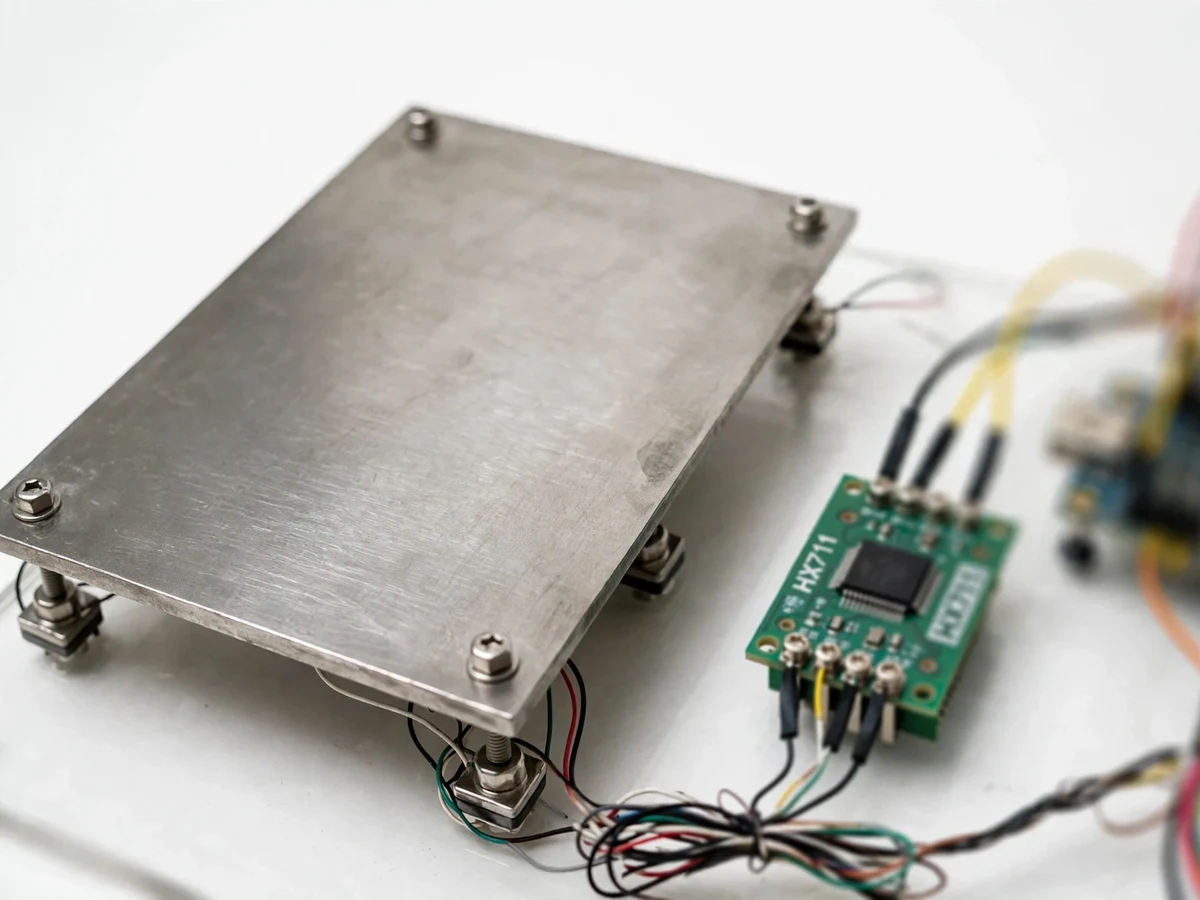
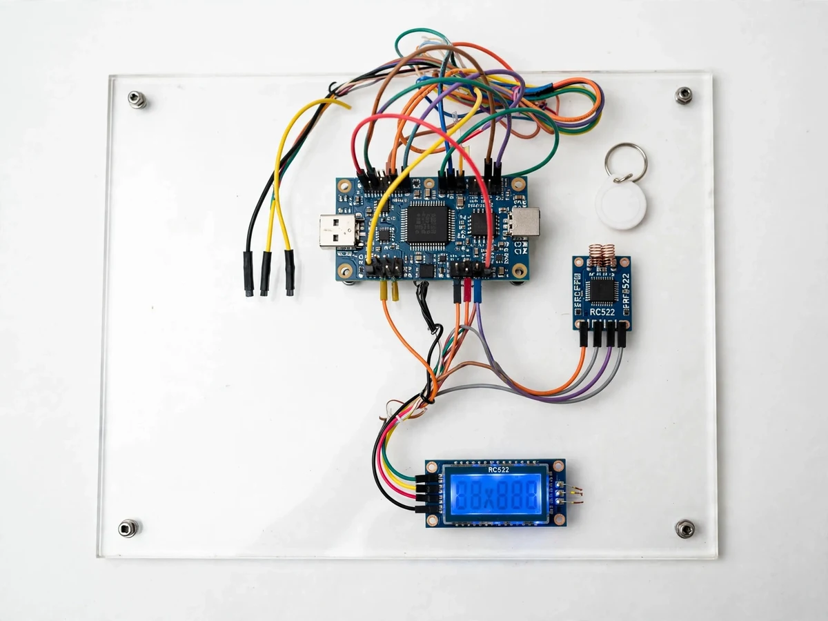
At quarries, warehouses and farm collection centers, every truck that enters and leaves must be weighed — and the weighing is still often a manual ritual: the operator reads a display, writes the number in a register, and mistakes, disputes and outright fraud creep in. An automated weighbridge fixes the weak link by tying each weight reading to a vehicle identity automatically: the truck drives on, the barrier-side RFID reader captures its tag, the load cells settle, and the weight is logged against that tag with a timestamp — no handwriting, no transcription error. This project builds that system at demonstrator scale: a steel platform on four button load cells, an HX711 precision amplifier, an ESP32 controller, an RC522 RFID reader and a 16x2 LCD, with firmware that handles tare, calibration and overload alarming and a cloud log of every tagged transaction.
How it works
- The platform is tared empty (or calibrated with a known weight per the included procedure) before the weighing session.
- A load is placed on the platform and the four load cells' signals are summed by the HX711 24-bit ADC.
- The ESP32 averages readings and waits for the value to stabilize within the configured tolerance band.
- The operator presents the RFID tag; the RC522 reader captures the tag ID.
- Weight, tag ID and timestamp are shown on the LCD and pushed to the cloud log over Wi-Fi.
- If the load exceeds the overload threshold, the buzzer sounds and the event is flagged in the log.
Tech stack:
- ESP32 development board (Arduino-IDE firmware, C++)
- 4× button load cells with HX711 24-bit ADC amplifier
- RC522 RFID reader module (13.56 MHz) with tags/cards
- 16x2 LCD display, buzzer, regulated 5 V power
- Cloud logging over Wi-Fi (HTTP/MQTT endpoint)
- Steel platform, acrylic base, wiring and mounting hardware
| Parameter | Value |
|---|---|
| Controller | ESP32 (Arduino-IDE firmware) |
| Weighing | 4× button load cells via HX711 24-bit ADC; multi-cell summation |
| Capacity | Design target: up to ~5 kg on the demonstrator platform (set by the load cells fitted at your build) |
| Resolution | HX711 24-bit ADC; usable resolution depends on cell rating and mechanical noise (buyer-calibrated) |
| RFID | RC522 13.56 MHz reader; tag ID bound to each transaction |
| Display | 16x2 character LCD (live weight, tag status, messages) |
| Connectivity | Wi-Fi to cloud log (HTTP/MQTT); LCD + local serial work offline |
| Functions | Tare, known-weight calibration, stable-reading detection, overload alarm with buzzer |
Project features
- [Four-cell weigh platform] A steel platform on four button load cells sums corner loads through the HX711 24-bit ADC, demonstrating real multi-cell weighing practice.
- [RFID vehicle tagging] An RC522 reader captures the RFID card/tag presented at weighing time and binds the tag ID to the weight record automatically.
- [Tare and calibration in firmware] One-button tare zeroes the platform, and a known-weight calibration routine sets the scale factor — the standard field procedure, implemented and documented.
- [16x2 LCD readout] Live weight, tag status and system messages on a blue-backlit LCD, so the demo runs standalone without a laptop.
- [Overload alarm] A configurable threshold triggers a buzzer and an LCD warning when the platform load exceeds the set limit.
- [Cloud transaction log] Every weighing — tag ID, weight, timestamp — is pushed over Wi-Fi to a cloud log the student can show, export and analyze.
- [Stable-reading detection] Firmware waits for the reading to settle within a tolerance band before logging, so vibrations don't corrupt the record.
What is included
- Assembled weighbridge prototype (platform, load cells, electronics, LCD, RFID reader)
- ESP32 firmware source code with comments
- Wiring diagram and full component list
- Calibration and tare procedure document (known-weight method)
- Cloud-log setup guide (endpoint configuration, log export)
- Project abstract PDF
- Project report (background, load-cell theory, firmware design, calibration results)
- PPT presentation and viva Q&A document (strain gauges, HX711, RFID, IoT logging)
Limitations & prerequisites
- This is a small demonstrator, not a trade-certified weighbridge: it is not legal-for-trade and cannot certify commercial transactions — the report states this explicitly.
- Accuracy depends on calibration with a known weight, level mounting and a vibration-free table; temperature drift and creep affect readings over time.
- The ~5 kg design capacity is set by the demonstrator's load cells; larger cells and a sturdier platform are possible as a customization.
- Cloud logging needs Wi-Fi; weighing, tare and the LCD readout work fully offline.
- Load cells are sensitive to shock loads and off-center placement — the setup guide covers handling precautions.
Frequently Asked Questions
Is this project suitable for a final-year project?
Yes — it suits Electronics, Instrumentation and IoT programs, demonstrating sensor interfacing, ADC signal chains, RFID integration, embedded firmware and cloud logging in one build.
Which controller and sensor chain are used?
An ESP32 reads four button load cells through an HX711 24-bit ADC amplifier; an RC522 module handles RFID tagging and a 16x2 LCD shows the weight.
How is it calibrated?
With the standard known-weight procedure: tare empty, place a known mass, and the firmware computes the scale factor. The full procedure ships with the project.
How accurate is it?
Accuracy depends on your calibration, mounting and environment — no figure is claimed ahead of your build. The report documents the calibration procedure and how to measure your own error.
Does it need internet?
Only for the cloud transaction log. Weighing, tare, calibration, RFID capture and the LCD all work offline.
Can it weigh trucks?
No — this is a ~5 kg demonstrator that models the real system's logic. The same architecture (cells + amplifier + controller + RFID + log) is what full-size weighbridges use, which is exactly the viva story. Suitable for B.E./B.Tech final-year projects in Electronics, Instrumentation and IoT.
Components & software requirements
- ESP32 development board (Arduino-IDE firmware, C++)
- 4× button load cells with HX711 24-bit ADC amplifier
- RC522 RFID reader module (13.56 MHz) with tags/cards
- 16x2 LCD display, buzzer, regulated 5 V power
- Cloud logging over Wi-Fi (HTTP/MQTT endpoint)
- Steel platform, acrylic base, wiring and mounting hardware
Delivery information
Built-to-order project. Delivery timeline is shared after order confirmation based on current queue.
Support terms
Complete documentation, setup guide, and viva preparation included. Support for setup and explanation provided.