
More project photos (2)
The problem
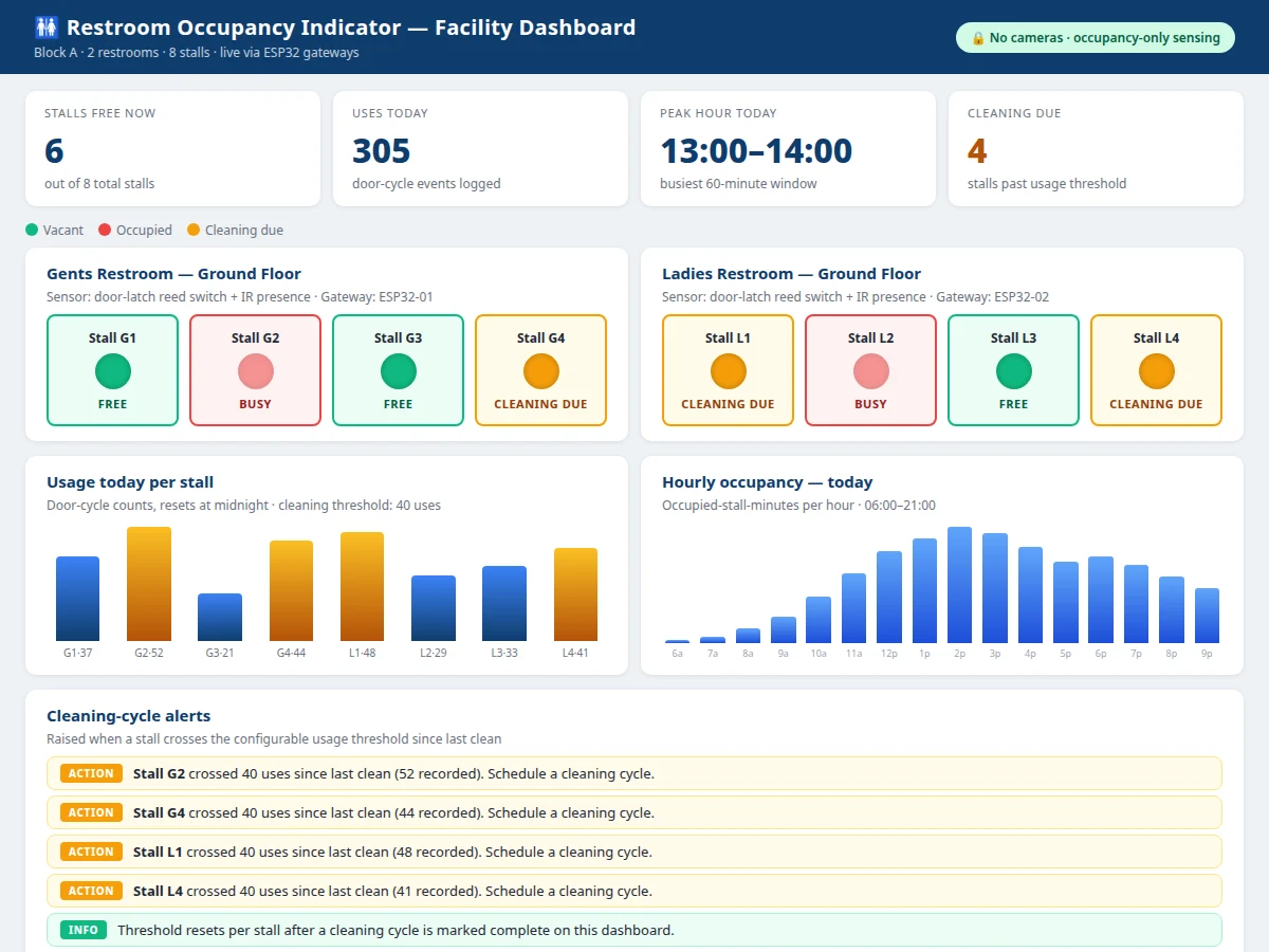
In malls, colleges, offices and transit hubs, queues form outside washrooms because visitors cannot tell which stalls are free — they wait at the entrance, push half-open doors, or walk away. Facility teams face the mirrored problem: cleaning rounds run on a fixed schedule, so high-traffic stalls get dirty between rounds while low-use ones are cleaned needlessly, and nobody has usage data to plan better. This project fixes both with per-stall occupancy sensing. A door-latch switch plus an IR proximity sensor reports each stall's state; an ESP32 gateway drives red/green indicators above every stall door and a corridor display showing the live free-stall count; and a web dashboard turns the stream into usage analytics — per-stall door-cycle counts, hourly occupancy patterns, peak-hour detection — with cleaning-cycle alerts when a stall crosses a configurable usage threshold. Critically, the sensing is occupancy-only: no cameras, no audio, no identity data. Privacy holds by architecture rather than policy, so the system is genuinely deployable in real institutional washrooms rather than just demoable in a lab.
How it works
- The reed switch on each stall latch reports locked/unlocked while the IR proximity sensor checks for a person inside.
- The ESP32 stall node fuses both signals into an occupied/vacant state with debounce (design target ~3 s) so door bumps don't flip the state.
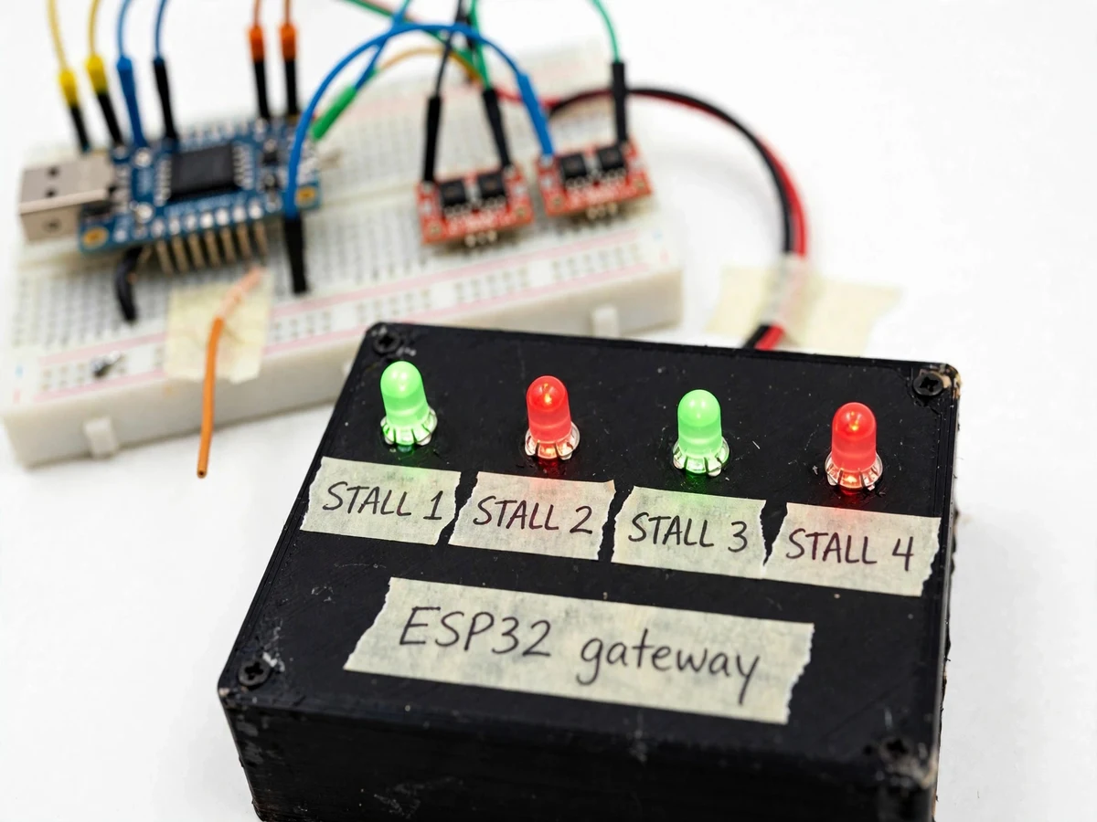
- The node drives the red/green LED above that stall's door and publishes the state change over Wi-Fi (MQTT) to the backend.
- The corridor display panel updates the live free-stall count within seconds of every state change.
- The backend logs each door-cycle event with a timestamp into the usage store.
- The dashboard renders the live occupancy grid, per-stall usage bars, hourly occupancy charts and the peak-hour window.
- When a stall's usage count since its last clean crosses the configured threshold (default 40, configurable), a cleaning-cycle alert appears on the dashboard until the stall is marked cleaned.
Tech stack:
- ESP32 (stall nodes + gateway, firmware in Arduino/ESP-IDF style C++)
- Reed switch · IR proximity sensor
- Red/green LED stall indicator panels
- Corridor display (MAX7219 LED matrix / OLED)
- MQTT · Wi-Fi telemetry
- Node.js backend with event store
- HTML · CSS · JS dashboard
- 5 V DC power adapters
| Parameter | Value |
|---|---|
| Stalls per gateway | Up to 8 (design target) |
| Door-to-dashboard latency | < 2 s typical (expected) |
| Debounce window | Approximately 3 s (configurable) |
| Telemetry | MQTT over Wi-Fi, store-and-forward across outages (design target) |
| Corridor display | Live free-stall count, updates on every state change |
| Dashboard | Live occupancy grid, per-stall and hourly usage charts, alert log |
| Cleaning threshold | Configurable usage count per stall, default 40 (expected) |
| Power | 5 V DC per node via USB adapter |
| Privacy | No cameras, no audio, no identity data — by architecture |
| Wireless range | Within Wi-Fi coverage of the washroom block (expected) |
Project features
- [Per-stall door-latch sensing] A reed switch on each stall's latch reports locked/unlocked state — the primary, positive occupancy signal straight from the door.
- [IR presence backup] An IR proximity sensor backs up the latch state, so an unlocked-but-occupied stall is not misread as free; both signals fuse with debounce.
- [Stall and corridor indicators] Red/green LEDs above each stall door plus a corridor panel showing the live free-stall count, so visitors see availability before queuing.
- [Live occupancy dashboard] A web dashboard mirrors every stall's state in real time over Wi-Fi/MQTT, with per-stall state history for the shift.
- [Usage analytics] Door-cycle counts per stall, hourly occupancy charts and peak-hour detection turn raw events into facility-usable insight.
- [Cleaning-cycle alerts] When a stall's usage count since its last clean crosses the configurable threshold, the dashboard raises an alert for the cleaning team; marking the stall cleaned resets its counter.
- [Privacy-first design] Occupancy-only sensing — no cameras, no audio, no identity data — so the system is acceptable in real washrooms, not just labs.
What is included
- Stall sensor modules: reed latch switch + IR proximity sensor with wiring per stall
- ESP32 node/gateway with firmware (sensing fusion, debounce, MQTT, display driver)
- Assembled corridor display panel (LED matrix/OLED) with mounting bracket
- Web dashboard with live occupancy grid, usage analytics and cleaning alerts
- Installation and door-mounting guide with sensor calibration procedure
- Project report PDF (sensing design, system architecture, methodology)
- PPT presentation and viva Q&A preparation document
Limitations & prerequisites
- Occupancy-only: the system reports stall states, not people — it cannot confirm the type of usage or count multiple occupants in one stall.
- No cameras by design, so analytics are limited to door-cycle counts and occupancy durations; no demographic or behavioural insight is possible.
- IR sensors can be affected by highly reflective surfaces or dust build-up; the installation guide includes a placement and verification procedure to run during calibration.
- Latch switches depend on correct door alignment — poorly aligned latches must be adjusted before sensing is reliable.
- Wi-Fi coverage is required across the washroom block for live updates; outages are bridged by store-and-forward (design target), not eliminated.
- Cleaning alerts are usage-based, not hygiene-based: a spill in a low-use stall still needs a manual report.
- Real public deployment should include signage that occupancy is monitored, and local privacy regulations should be checked.
Frequently Asked Questions
Does it use cameras or record people?
No — sensing is occupancy-only. A latch reed switch plus an IR proximity sensor report locked/unlocked and presence states. No images, no audio, no identity data is ever captured or stored.
How reliable is the occupancy detection?
The latch switch gives the primary signal and the IR sensor backs it up, fused with a ~3 s debounce so door bumps don't flip the state. Exact reliability depends on door alignment and calibration, both covered in the installation guide.
How do cleaning-cycle alerts work?
Each stall's door-cycle count resets when it is marked cleaned; crossing the configurable threshold (default 40) raises an alert on the dashboard for the facility team.
What does the corridor display show?
The live count of free stalls, updating within seconds of every state change — visitors know availability before they queue.
Can it work without the dashboard?
Yes. The corridor display and stall LEDs run from the ESP32 gateway alone; the dashboard adds event logging, analytics and the cleaning alerts.
Is this project suitable for a final-year project?
Yes — for Electronics, E&TC and IoT & Embedded programs. It combines embedded sensing, firmware design, wireless telemetry and a genuinely useful analytics dashboard around a real facility problem. Suitable for B.E./B.Tech final-year projects in Electronics and IoT & Embedded Systems.
Components & software requirements
- ESP32 (stall nodes + gateway, firmware in Arduino/ESP-IDF style C++)
- Reed switch · IR proximity sensor
- Red/green LED stall indicator panels
- Corridor display (MAX7219 LED matrix / OLED)
- MQTT · Wi-Fi telemetry
- Node.js backend with event store
- HTML · CSS · JS dashboard
- 5 V DC power adapters
Delivery information
Built-to-order project. Delivery timeline is shared after order confirmation based on current queue.
Support terms
Complete documentation, setup guide, and viva preparation included. Support for setup and explanation provided.