
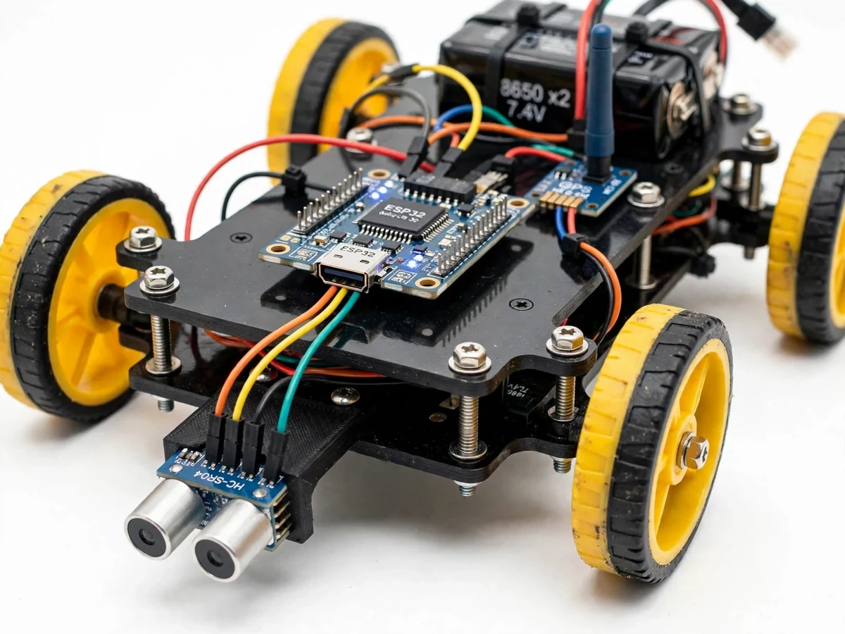
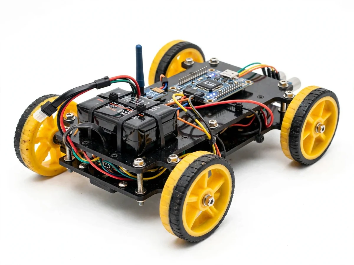
More project photos (2)
The problem
Potholes damage vehicles and cause accidents, yet road-condition surveys in most cities are still manual, infrequent and subjective — an inspector drives a stretch and notes defects by eye. A low-cost sensing unit on ordinary vehicles could make defect reporting continuous and location-accurate: measure the road profile, flag sudden dips and bumps, attach GPS coordinates, and stream the events to a map the municipality can act on. This project builds the sensing-and-telemetry half of that vision at student scale: an ultrasonic sensor profiles the road surface, an accelerometer confirms the jolt, and an ESP32 publishes geo-tagged events to a live dashboard. The scope is honest — a demonstrator on a model vehicle, not a certified road-survey instrument — but the pipeline (sensing, fusion, geo-tagging, cloud map) is the real architecture such systems use.
How it works
- The HC-SR04 continuously measures the distance from the vehicle underside to the road surface.
- A rolling baseline of the road distance is maintained; deviations beyond the configured depth threshold start a candidate event.
- The MPU6050's vertical acceleration is checked for a matching jolt spike within the same window to confirm the event.
- The ESP32 reads the NEO-6M GPS for latitude and longitude and packages the event as JSON.
- The event is published over Wi-Fi/MQTT to the broker and appended to the microSD backup log.
- The dashboard subscribes to the event topic and drops a marker on the live map with depth, jolt and timestamp.
Tech stack:
- ESP32-WROOM-32, firmware in Arduino IDE (C++)
- HC-SR04 ultrasonic sensor (2–400 cm, ~±3 mm typical)
- MPU6050 accelerometer (jolt cross-check)
- NEO-6M GPS module (UART, NMEA)
- MQTT telemetry (Mosquitto broker)
- Node-RED/Blynk live map dashboard
- microSD event backup log
- 5 V vehicle power (buck converter from 12 V)
| Parameter | Value |
|---|---|
| Controller | ESP32-WROOM-32 (Wi-Fi, dual-core) |
| Road sensor | HC-SR04 ultrasonic, 2–400 cm range, ~±3 mm typical accuracy, ~15° beam angle |
| Jolt sensor | MPU6050 triaxial accelerometer, vertical-axis spike confirmation |
| GPS | u-blox NEO-6M; ~2.5 m CEP horizontal accuracy (datasheet), open sky required |
| Connectivity | Wi-Fi to MQTT broker (Mosquitto); GSM via SIM800L as optional customization |
| Dashboard | Node-RED/Blynk live map with event markers, depth and jolt values |
| Backup log | microSD card: timestamp, lat/lon, depth deviation, jolt peak |
| Power | 5 V from vehicle USB or 12 V buck converter |
| Mount | Adjustable bracket for a model demo vehicle |
Project features
- [Ultrasonic road profiling] A downward-facing HC-SR04 (2–400 cm range, ~±3 mm typical accuracy) measures road distance; sudden increases flag potholes, sudden decreases flag bumps.
- [Accelerometer cross-check] The MPU6050's vertical-axis spike confirms the jolt, filtering out ultrasonic noise and momentary echoes.
- [GPS geo-tagging] A NEO-6M module stamps latitude and longitude on every confirmed event.
- [MQTT telemetry and live map] The ESP32 publishes events to an MQTT broker; a Node-RED/Blynk dashboard plots them as map markers in real time.
- [On-device event log] A microSD card backs up every event with timestamp and coordinates when Wi-Fi is unavailable.
- [Configurable thresholds] Pothole depth threshold and jolt g-threshold are set via a configuration file and dashboard controls — no firmware change needed.
- [Demo vehicle mount] An adjustable bracket fits the unit to a model car, powered from 5 V USB or a 12 V buck converter.
What is included
- Assembled sensing unit (ESP32, sensors, GPS, mount)
- ESP32 firmware source code with comments
- MQTT + dashboard setup guide
- Wiring diagram and component list
- Threshold-tuning procedure document
- Project abstract PDF
- Project report (background, sensor fusion logic, methodology, demo results)
- PPT presentation and viva Q&A document
Limitations & prerequisites
- This is a demo-scale build on a model vehicle; validation at real traffic speeds on public roads is outside the project's scope.
- The HC-SR04's ~15° beam and speed-dependent echo quality limit it; wet or soft surfaces absorb sound and weaken returns.
- Rough-but-healthy roads can trigger false positives — thresholds need tuning for each surface, documented in the tuning guide.
- GPS needs open sky; urban canyons and flyovers degrade fix quality.
- Live telemetry needs a Wi-Fi hotspot in the vehicle; without it, events accumulate only on the SD card (GSM uplink is an optional add-on).
Frequently Asked Questions
Is this project suitable for a final-year project?
Yes — for Electronics, IoT and Computer Engineering programs, demonstrating sensor fusion, embedded networking, GPS handling and dashboard visualization.
How does it tell a pothole from a bump?
A pothole shows as a sudden increase in measured road distance, a bump as a sudden decrease; the accelerometer's jolt direction cross-checks the classification.
Does it work at real driving speeds?
It is validated at demo-vehicle speeds. Real-road, traffic-speed operation would need a faster sensor, rugged mounting and field trials — stated as future scope.
Does it need internet?
Only for the live map: the unit needs a Wi-Fi hotspot to publish. Without connectivity it keeps logging to the SD card for later upload.
Can it use GSM instead of Wi-Fi?
Yes — a SIM800L GSM uplink is a supported optional customization for areas without Wi-Fi.
What are the main limitations?
Demo scale, ultrasonic physics limits, surface-dependent tuning, GPS sky view and hotspot dependence — detailed under Limitations. Suitable for B.E./B.Tech final-year projects in Electronics, IoT and Computer Engineering.
Components & software requirements
- ESP32-WROOM-32, firmware in Arduino IDE (C++)
- HC-SR04 ultrasonic sensor (2–400 cm, ~±3 mm typical)
- MPU6050 accelerometer (jolt cross-check)
- NEO-6M GPS module (UART, NMEA)
- MQTT telemetry (Mosquitto broker)
- Node-RED/Blynk live map dashboard
- microSD event backup log
- 5 V vehicle power (buck converter from 12 V)
Delivery information
Built-to-order project. Delivery timeline is shared after order confirmation based on current queue.
Support terms
Complete documentation, setup guide, and viva preparation included. Support for setup and explanation provided.