
More project photos (2)
The problem
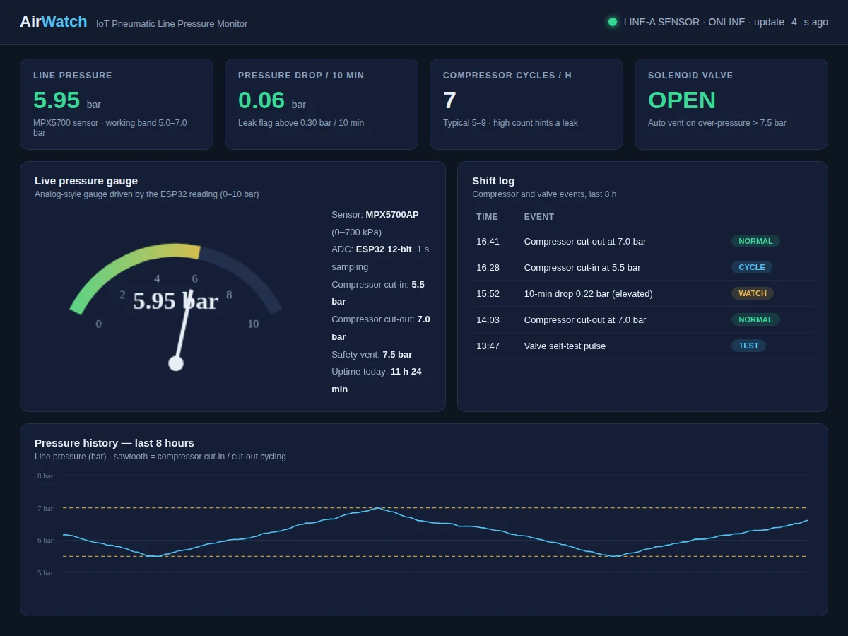
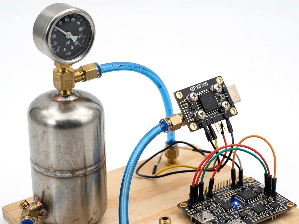
Pneumatic lines run factory automation — cylinders, grippers, blow-offs — and their health shows in one number: pressure. A slow leak wastes compressor energy and makes actuators sluggish; an over-pressure event risks burst fittings. Maintenance teams watch gauges, but gauges don't log, don't alert and don't count compressor cycles. This project instruments a small air line properly: an MPX5700 pressure sensor teed into the line, an ESP32 sampling it every second, and a dashboard showing a live gauge, the shift's pressure history, compressor cut-in/cut-out cycles and a leak-watch flag computed from pressure drop over 10-minute windows. A solenoid valve vents the line if pressure crosses the safety limit. The student learns pressure sensing, calibration against a gauge, threshold logic and the full IoT telemetry loop — on hardware that behaves like a real workshop line.
How it works
- The MPX5700 sensor is teed into the small air line with pneumatic fittings; its analog output feeds the ESP32 ADC.
- The ESP32 samples pressure every second, applies the two-point calibration, and publishes the reading over Wi-Fi (MQTT/HTTP).
- The dashboard renders the live gauge, appends to the 8-hour history chart, and evaluates the reading each cycle.
- Crossing the cut-out pressure logs a compressor stop; crossing cut-in logs a start — the cycle counter increments per hour.
- Every 10 minutes the firmware computes the pressure drop; if it exceeds the leak threshold, the dashboard raises a leak-watch flag.
- If pressure crosses the safety limit, the ESP32 energizes the solenoid valve to vent the line until pressure falls back.
- The student introduces a controlled small leak (a loosened fitting) and watches the cycle count and drop metric respond.
Tech stack:
- ESP32 development board (Wi-Fi)
- MPX5700AP pressure sensor (0-700 kPa)
- Small air receiver / compressor line with analog gauge
- Solenoid valve for safety vent
- Pneumatic tubing and tee fittings
- MQTT broker + web dashboard (HTML/JS)
- Arduino IDE (C/C++ firmware)
| Parameter | Value |
|---|---|
| Pressure sensor | MPX5700AP piezoresistive, 0-700 kPa range |
| Sampling | 1 Hz via ESP32 12-bit ADC |
| Working band (design) | 5.0-7.0 bar; cut-in 5.5, cut-out 7.0, safety vent 7.5 bar |
| Calibration | Two-point against analog gauge, buyer-run |
| Leak metric | Pressure drop per 10-min window; watch flag above threshold |
| Safety | Solenoid vent on over-pressure |
| Dashboard | Live gauge, 8-h history, cycle counter, event log |
Project features
- [MPX5700 pressure sensing] Piezoresistive sensor teed into the air line; ESP32 reads it every second through its 12-bit ADC.
- [Live gauge dashboard] Analog-style gauge plus digital readout, updating live over Wi-Fi with 8-hour pressure history.
- [Compressor cycle counting] Cut-in/cut-out detection counts cycles per hour — a rising count is the classic leak indicator.
- [Leak-watch detection] Pressure drop per 10-minute window is computed; crossing the leak threshold raises a watch flag on the dashboard.
- [Solenoid safety vent] On over-pressure the ESP32 drives a solenoid valve to vent the line — a demonstrable safety interlock.
- [Gauge calibration] The student calibrates the sensor reading against the analog gauge with a two-point procedure.
- [Shift event log] Compressor cycles, valve tests and leak watches are logged with timestamps.
What is included
- Working pneumatic pressure monitor (sensor node, line hardware, dashboard)
- Complete ESP32 firmware source code (sampling, calibration, MQTT, valve logic)
- Dashboard web app (gauge, history, cycle counter, event log)
- Plumbing and wiring documentation
- Two-point calibration procedure
- Leak-detection experiment guide
- Project report PDF (pressure sensing, pneumatics, IoT pipeline, experiment)
- PPT presentation for final review
- Viva Q&A preparation document (piezoresistive sensing, calibration, leak detection, MQTT)
- Setup and demonstration guide
Limitations & prerequisites
- Demo-scale line only — small receiver and low pressures; not a plant air system and not rated for industrial pressures.
- Leak detection is indicative (pressure-drop heuristic), not a calibrated flow measurement; thresholds are set by the student's experiment.
- The solenoid vent is a demonstration interlock, not a certified pressure-relief device; a mechanical relief valve remains the real safety.
- Wi-Fi dropouts pause the dashboard feed; the node does not buffer long outages in the base build.
- Sensor accuracy follows the MPX5700 datasheet; the two-point calibration corrects offset and span on the student's rig.
Frequently Asked Questions
How does it detect leaks?
Two ways: the 10-minute pressure-drop metric (a tight line holds pressure; a leak shows as steady drop) and the compressor cycle count (more cycles per hour means air is escaping somewhere). The student verifies both with a controlled leak.
How is the sensor calibrated?
Two-point procedure: read the sensor at two known pressures from the analog gauge, and the firmware maps the ADC range to bar. The student performs it on their own hardware.
What does the solenoid valve do?
It is a safety vent — if line pressure crosses the safety limit, the ESP32 opens the valve to vent air until pressure recovers. It demonstrates interlock logic, not certified relief.
What pressures does it handle?
Demo scale: working band 5.0-7.0 bar on a small receiver, within the MPX5700's 0-700 kPa range. Not for industrial plant air.
What are the main limitations?
Demo-scale pressures, heuristic (not calibrated) leak detection, demonstration-grade safety vent, no outage buffering, and datasheet-grade sensor accuracy.
Is this project suitable for a final-year project?
Yes — for Mechatronics, Mechanical and IoT programs. It demonstrates pressure sensing, calibration, pneumatics and IoT telemetry, all strong viva material. Suitable for B.E./B.Tech final-year projects in Mechatronics, Mechanical and IoT engineering.
Components & software requirements
- ESP32 development board (Wi-Fi)
- MPX5700AP pressure sensor (0-700 kPa)
- Small air receiver / compressor line with analog gauge
- Solenoid valve for safety vent
- Pneumatic tubing and tee fittings
- MQTT broker + web dashboard (HTML/JS)
- Arduino IDE (C/C++ firmware)
Delivery information
Built-to-order project. Delivery timeline is shared after order confirmation based on current queue.
Support terms
Complete documentation, setup guide, and viva preparation included. Support for setup and explanation provided.