
More project photos (2)
The problem
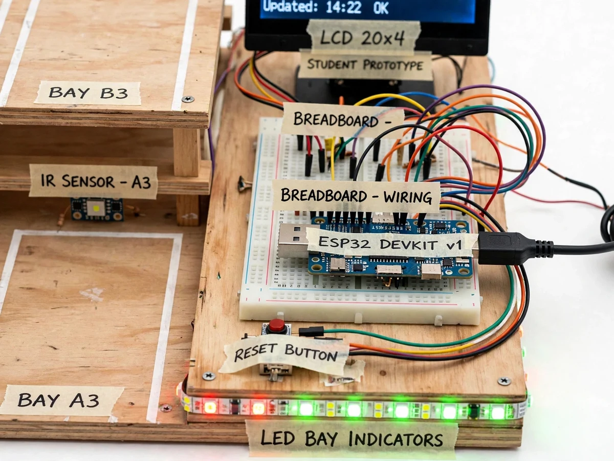
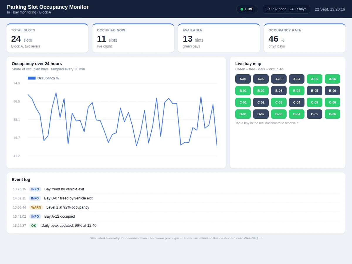
Drivers in malls, campuses and office basements waste time circling for a free slot while attendants guess at availability. The sensing problem is simple but unforgiving: each bay needs a reliable occupied/free decision, states must reach the dashboard in seconds, and the entry display must agree with reality or drivers stop trusting it. This project solves it with an IR reflective sensor per bay on a scaled parking model — 24 bays across two levels — wired to ESP32 nodes that publish bay states over Wi-Fi via MQTT. A web dashboard renders the live bay map, occupancy percentage and hourly trends, and a 20x4 LCD at the model entry shows free-bay counts per level. The project is honest about sensing limits: IR detection range and ambient-light interference are documented, and a calibration procedure for sensor thresholds is part of the deliverable.
How it works
- The IR sensor on each bay continuously measures reflected infrared; firmware compares the reading against a calibrated threshold to decide occupied or free.
- On every state change (with debounce), the ESP32 publishes the bay ID and new state as a JSON message over Wi-Fi via MQTT.
- The dashboard backend stores each event with a timestamp and re-renders the live bay map, per-level counts and occupancy percentage.
- Hourly aggregation jobs build the trend graphs: occupancy curve, peak hours and average dwell time per bay.
- The entry LCD polls the same state store and refreshes free-bay counts per level on a 5-second design-target cycle.
- When occupancy on a level crosses the configured alert threshold, the dashboard raises a banner and logs the event for the analytics view.
- The calibration routine walks the operator through setting each sensor's threshold with a vehicle present and absent, storing values in EEPROM.
Tech stack:
- ESP32 development boards (2 nodes)
- IR reflective sensor modules x24 (adjustable)
- 20x4 LCD with I2C backpack (entry display)
- MQTT broker + web dashboard
- Arduino IDE (C/C++ firmware)
- 5 V regulated power distribution
- Scaled two-level bay model with wiring trunking
- Buzzer + status LEDs
| Parameter | Value |
|---|---|
| Controller | 2x ESP32, Wi-Fi MQTT telemetry (JSON bay events) |
| Bays monitored | 24 bays across 2 levels (design target) |
| Sensor | IR reflective module, adjustable range approximately 2-30 cm |
| State latency | Under 5 s from bay change to dashboard (design target) |
| Dashboard | Live bay map, occupancy %, hourly trends, alerts |
| Entry display | 20x4 LCD, free-bay counts per level |
| Power | 5 V DC regulated, approximately 2 A peak (expected) |
| Calibration | Per-sensor threshold routine stored in EEPROM |
Project features
- [Per-bay IR sensing] Each of the 24 bays carries an adjustable IR reflective sensor that reports occupied or free; firmware debounces transitions so a passing shadow does not flip a bay state.
- [Live availability dashboard] A web dashboard shows the bay map in real time — green for free, dark for occupied — plus occupancy percentage, free-bay counts per level and hourly trend graphs.
- [Entry guidance display] A 20x4 LCD mounted at the model entrance shows live free-bay counts per level, so the demo mirrors how a real deployment guides drivers.
- [MQTT telemetry] ESP32 nodes publish bay-state changes as JSON over Wi-Fi via MQTT with a design-target update latency under 5 seconds and automatic reconnect handling.
- [Occupancy analytics] The dashboard computes peak-occupancy hours, average dwell time and daily utilization from the stored bay-state history.
- [Threshold alerts] Configurable alerts fire when a level crosses 90% occupancy or when a sensor stops reporting, flagging a possible fault.
- [Scaled physical model] The hardware is a two-level parking bay model with marked bays, sensor mounts and wiring trunking — a realistic demonstration rig, not loose parts on a bench.
What is included
- Working 24-bay parking model with IR sensors, ESP32 nodes and entry LCD
- Complete firmware source (sensing, debounce, MQTT, LCD driver)
- Live web dashboard (bay map, trends, alerts) demonstrated with the model
- Circuit and wiring documentation with sensor calibration procedure
- Component list with ratings
- Project report PDF (parking guidance background, IoT architecture, methodology, test procedure)
- PPT presentation for final review
- Viva Q&A preparation document (IR sensing, MQTT, debouncing, analytics)
- Setup and demonstration guide
Limitations & prerequisites
- IR sensors report presence, not vehicle identity — number-plate recognition is out of scope.
- Strong direct sunlight on the sensor face can shift thresholds; the model is demonstrated indoors and calibration is per-installation.
- Detection is binary per bay; the system does not measure vehicle size or detect double-parking across bays.
- Dashboard and LCD need the same Wi-Fi network as the nodes; internet outages pause cloud history but local states persist on the nodes.
- 24 bays is the design target for the demonstration model; a real deployment would add per-node addressing and power budgeting.
Frequently Asked Questions
How does the system know a bay is occupied?
Each bay has an IR reflective sensor aimed at the parking surface. When a vehicle is present, reflected IR rises above the calibrated threshold and firmware marks the bay occupied after a debounce window; when it falls back, the bay is marked free. Thresholds are set per sensor during the calibration routine.
What does the dashboard show?
A live bay map with every bay coloured free or occupied, occupancy percentage, free-bay counts per level, hourly occupancy trends, peak-hour analysis and average dwell time — plus configurable alerts for high occupancy or silent sensors.
How fast does the dashboard update?
Bay-state changes are published over MQTT immediately with a design-target end-to-end latency under 5 seconds; the entry LCD refreshes on a 5-second cycle from the same state store.
Can it handle a bigger parking lot?
The architecture scales — more ESP32 nodes publish to the same broker and the dashboard aggregates by level or zone. The 24-bay model demonstrates the pattern; power and network planning for a real lot are covered as future scope in the report.
What are the main limitations?
IR sensing is presence-only with no vehicle identification, strong sunlight needs recalibration, the demo is a 24-bay indoor model, and cloud history pauses if the network drops.
Is this project suitable for a final-year project?
Yes — for IoT and Embedded Systems programs. It covers multi-node sensing, MQTT telemetry, a real-time dashboard, a physical demonstration model and honest calibration, all strong viva material. Suitable for B.E./B.Tech final-year projects in IoT and Embedded Systems.
Components & software requirements
- ESP32 development boards (2 nodes)
- IR reflective sensor modules x24 (adjustable)
- 20x4 LCD with I2C backpack (entry display)
- MQTT broker + web dashboard
- Arduino IDE (C/C++ firmware)
- 5 V regulated power distribution
- Scaled two-level bay model with wiring trunking
- Buzzer + status LEDs
Delivery information
Built-to-order project. Delivery timeline is shared after order confirmation based on current queue.
Support terms
Complete documentation, setup guide, and viva preparation included. Support for setup and explanation provided.