
More project photos (2)
The problem
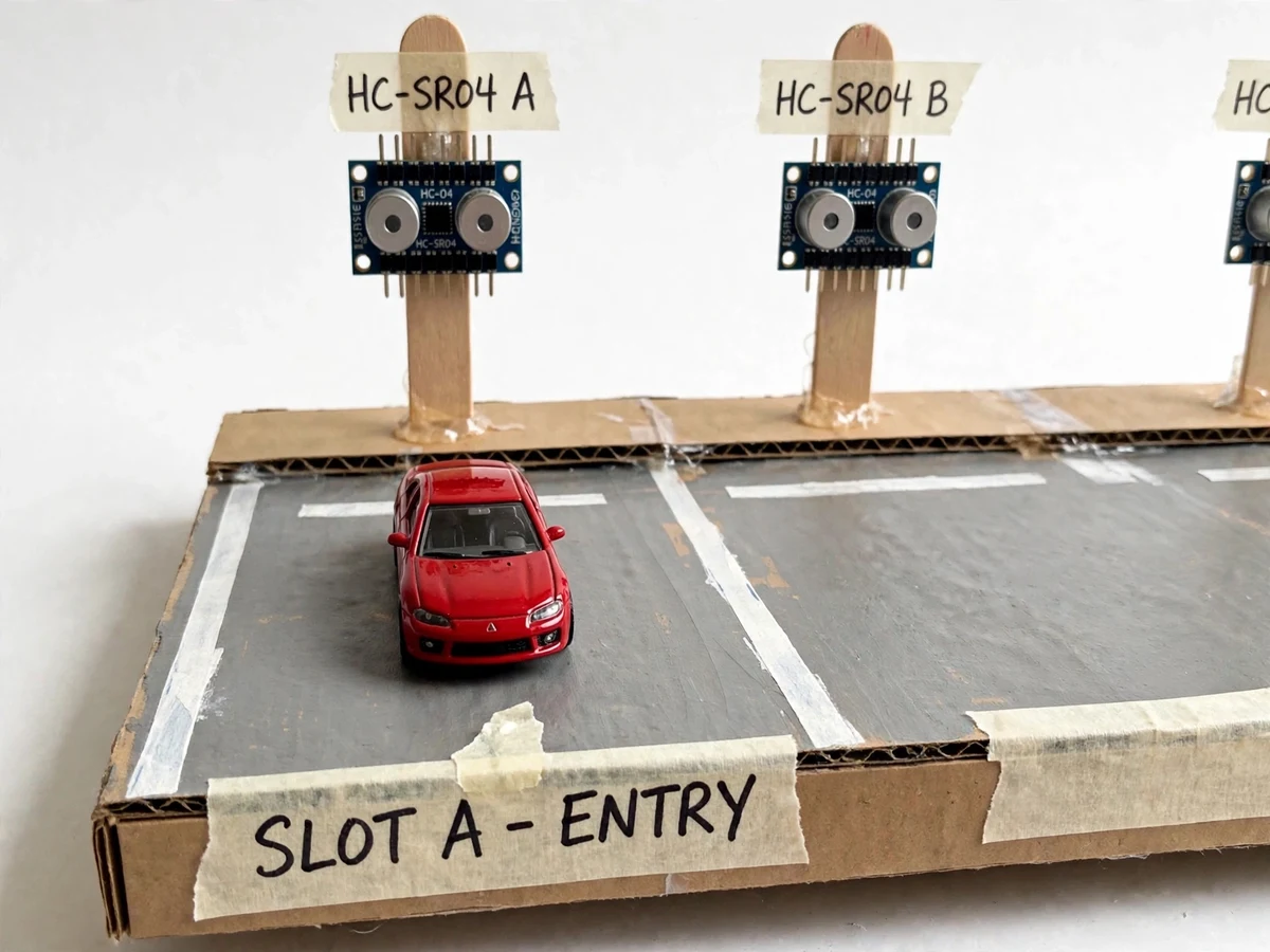
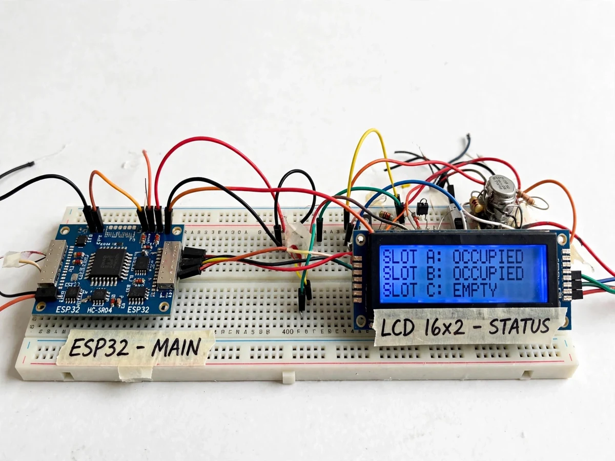
Drivers circling a lot looking for a free slot waste fuel and time, while lot operators have no live picture of occupancy. An ultrasonic sensor aimed at each slot answers the question directly: a short echo means a car is there. The engineering work is in polling several sensors without crosstalk, the occupied/free threshold and the live display. This project builds a student-scale IoT parking monitor on an ESP32: three demo slots each get an HC-SR04 ultrasonic sensor on a post, the ESP32 polls them in sequence, an LCD shows the free-slot count, a green/red LED per slot shows its state, and the slot map publishes to a phone dashboard over Wi-Fi.
How it works
- The ESP32 triggers each HC-SR04 in turn and measures the echo time, converting it to distance for that slot.
- Each distance is compared against the calibrated occupied threshold; readings below it mark the slot occupied, above it free.
- A debounce count requires the state to persist across several polls before it flips, so a walking person doesn't toggle a slot.
- The LCD updates with the free-slot count and per-slot states, and the post LEDs switch green or red to match.
- On every state change (and a periodic heartbeat) the ESP32 publishes the slot map to the phone dashboard over Wi-Fi.
- The buyer runs the included calibration procedure once to set the threshold for their exact demo geometry.
Tech stack:
- ESP32 development board
- HC-SR04 ultrasonic sensors (one per slot)
- 16x2 character LCD
- Green/red LED indicators
- Blynk-style IoT dashboard (phone slot map)
- Arduino IDE (C/C++ firmware)
- 5 V regulated power supply
| Parameter | Value |
|---|---|
| Controller | ESP32 development board |
| Slots (demo) | 3, each with dedicated HC-SR04 |
| Sensing range | HC-SR04 datasheet approximately 2–400 cm |
| Polling | Sequential, anti-crosstalk (design) |
| Display | 16x2 LCD + per-slot LEDs |
| Dashboard | Wi-Fi phone slot map |
| Power | 5 V regulated supply (design) |
Project features
- [Per-slot ultrasonic sensing] Each demo slot has its own HC-SR04 sensor measuring the distance to whatever is parked there.
- [Occupied/free threshold logic] Firmware compares each reading against a calibrated distance threshold to decide the slot state, with debouncing against passing movement.
- [LCD availability display] A 16x2 LCD shows the number of free slots and the per-slot status at a glance.
- [Per-slot LED indicators] A green/red LED pair at each slot post mirrors its state for the demo audience.
- [Wi-Fi slot map] The ESP32 publishes the live slot map to a phone dashboard over Wi-Fi for remote checking.
- [Sequential sensor polling] Sensors are polled one at a time in firmware to avoid ultrasonic crosstalk between adjacent posts.
- [Threshold calibration procedure] A buyer-run procedure sets the occupied distance for the demo geometry, documented in the report.
What is included
- Working model parking lot with three ultrasonic sensor posts, ESP32, LCD and LEDs
- Complete firmware with commented polling, threshold and telemetry logic
- Phone dashboard setup guide with screenshots
- Threshold calibration procedure
- Wiring diagram and connection table
- Project report PDF (background, system design, firmware logic, IoT architecture)
- PPT presentation for final review
- Viva Q&A preparation document (ultrasonic sensing, ESP32, threshold logic, IoT dashboards)
Limitations & prerequisites
- The demo covers three model slots — a real lot would need one sensor per slot plus weatherproofing and power distribution, which is outside the student scope.
- Ultrasonic readings are affected by temperature, angled surfaces and soft materials; the threshold is tuned for the demo geometry, not universal.
- Detection latency and accuracy are design targets verified on the buyer's own build; no certified figures are claimed.
- Wi-Fi dashboard updates depend on the buyer's own network and the third-party service; no uptime is guaranteed for external services.
- The system reports occupancy only — it cannot identify vehicles or enforce reservations.
- Battery or solar operation is not included; the unit runs on a 5 V adapter.
Frequently Asked Questions
How does it know a slot is occupied?
Each slot's ultrasonic sensor measures the distance to the nearest object. A reading below the calibrated threshold means a car is parked there; above it means the slot is free.
Don't the sensors interfere with each other?
They would if fired together, so the firmware polls them one at a time in sequence — the report explains this anti-crosstalk design.
How do I see the slot status remotely?
The ESP32 publishes the live slot map to a phone dashboard over Wi-Fi. The setup guide walks through connecting it to the buyer's own network.
Can it scale to a real parking lot?
The sensing principle scales, but a real deployment needs weatherproof sensors, per-slot power and networking — the report lists this honestly as beyond the demo scope.
What if someone just walks through a slot?
Firmware debouncing requires the occupied reading to persist across several polls before the state flips, so passing movement doesn't toggle the display.
Is this project suitable for a final-year project?
Yes — for Electronics and IoT & Embedded programs. It covers multi-sensor interfacing, threshold and debounce logic, and a complete device-to-dashboard IoT loop. Suitable for B.E./B.Tech final-year projects in Electronics and IoT & Embedded.
Components & software requirements
- ESP32 development board
- HC-SR04 ultrasonic sensors (one per slot)
- 16x2 character LCD
- Green/red LED indicators
- Blynk-style IoT dashboard (phone slot map)
- Arduino IDE (C/C++ firmware)
- 5 V regulated power supply
Delivery information
Built-to-order project. Delivery timeline is shared after order confirmation based on current queue.
Support terms
Complete documentation, setup guide, and viva preparation included. Support for setup and explanation provided.