
More project photos (2)
The problem
City noise is pollution you cannot see, and it is getting worse: traffic, construction, loudspeakers and late-night activity push residential areas far past healthy limits, with documented links to stress, poor sleep and hearing damage. Yet unlike air quality, noise has almost no public measurement infrastructure — complaints are subjective, enforcement is rare, and nobody can point at a number and say this street is louder than that one. Professional sound-level meters solve the measurement part but are single-point, expensive instruments that produce no maps and no history. What cities, campuses and housing societies actually need is a network of cheap, calibrated sensors streaming decibel readings to a shared dashboard: live levels, 24-hour trends and automatic alerts when silent zones near schools and hospitals are breached. This project builds exactly that with ESP32 nodes and MAX4466 microphone modules, with a two-point calibration procedure against a reference meter so the numbers are honest.
How it works
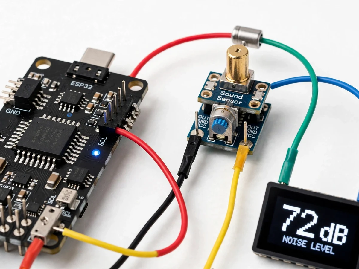
The MAX4466 electret microphone module captures ambient sound and the ESP32 samples its analog output in fast bursts.
Firmware computes the RMS voltage over each sampling window and maps it to dB SPL using the two-point calibration curve you set during your build-time calibration.
An A-weighting-style frequency correction is applied so the reading approximates human-perceived loudness, then 1-minute and 5-minute averages are computed.
The OLED refreshes with the live dB value, trend arrow and alert state; every reading is pushed over WiFi to the cloud dashboard.
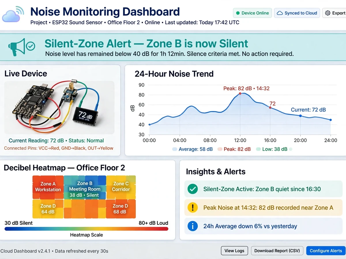
The dashboard plots the dB heatmap and 24-hour trend graphs; when a reading crosses the configured silent-zone limit, an alert notification is raised.
Deployed nodes each appear as separate map points, so a campus or street section gets a genuine noise map.
Project features
Live decibel measurement across a ~30–120 dB SPL range using MAX4466 microphone amplifier modules
Two-point calibration against a reference sound-level meter, documented with the calibration procedure and error-source analysis
A-weighting-style correction in firmware so readings reflect human-perceived loudness
0.96" OLED live display showing current dB, 1-minute average and alert status
Cloud dashboard with live dB map/heatmap, 24-hour trend graphs and per-node tiles
Silent-zone threshold alerts (e.g. 50 dB hospital/school limits) via dashboard notification and email
Multi-node ready — firmware supports several ESP32 sensor nodes feeding one shared dashboard
Min/average/max logging per interval with CSV export for report charts
Offline resilience — sensing and OLED keep working without WiFi; readings sync when the network returns
Adjustable sampling and upload intervals with deep-sleep scheduling for battery field deployments
What is included
Fully assembled noise monitoring unit
Complete firmware source code (Arduino IDE, well-commented)
Circuit diagram and wiring schematic
Calibration procedure sheet (two-point method vs reference meter)
Project report PDF (synopsis, design, calibration procedure, noise-map analysis, conclusion)
PPT presentation for final review
Viva Q&A preparation document (dB SPL theory, RMS math, calibration, A-weighting)
Cloud dashboard setup guide + sample CSV log exports for report charts
FAQs
- How accurate is it compared to a professional sound-level meter? After you complete the included two-point calibration, the unit should track a reference meter closely — the exact error depends on your own build. The report documents the calibration procedure and the error sources, so you can quote honest numbers instead of claiming meter-grade accuracy.
- How does the dB calibration work? We calibrate in two steps: record the sensor's raw output against a reference meter at a quiet level and a loud level, then the firmware fits a curve through both points. You repeat this once per deployment spot — the procedure is documented for the viva.
- What counts as a silent-zone violation? CPCB silent-zone limits are 50 dB (day) / 40 dB (night) for hospitals and schools. The dashboard lets you set any threshold; the demo ships preset with silent-zone defaults so alerts trigger visibly.
- Can I place multiple nodes around campus? Yes — the firmware supports several ESP32 nodes, each reporting to the same dashboard with its own map point and trend line. Multi-node noise mapping is one of the strongest extensions of this build.
- Does it work without WiFi? Sensing, dB computation and the OLED display run entirely locally, so the unit still functions as a standalone meter. Only the cloud map, trends and alerts pause until WiFi returns.
- How can I extend this project? Common extensions include: machine-classification of noise sources (traffic vs construction vs loudspeaker), wind-noise filtering, LoRa long-range nodes, and automatic complaint-report generation for municipal dashboards.
Limitations & prerequisites
Built on a consumer microphone module, not a Class 1/2 sound-level meter — calibrated readings are typically within ±2–3 dB of a reference meter, not legal-compliance grade.
Outdoor readings are affected by wind; a foam windscreen helps but gusts will spike the dB value.
Requires a reference sound-level meter (or a calibrated phone app as a rough proxy) for the two-point calibration step.
Cloud features need a stable 2.4 GHz WiFi connection; sensing and the OLED display keep working offline.
Components & software requirements
ESP32 DevKit microcontroller (WiFi 802.11 b/g/n, dual-core 240 MHz)
MAX4466 electret microphone amplifier modules (adjustable gain, analog output); KY-038 digital-threshold module for alarm input
0.96" I2C OLED display for live dB readout
Firmware: Arduino IDE / ESP-IDF (ADC burst sampling, RMS computation, calibration curve, A-weighting approximation)
Cloud dashboard: WiFi → MQTT/HTTP to web dashboard with live dB map, trend graphs and alert rules
5 V USB or battery power with optional deep-sleep scheduling
Specifications
| Parameter | Value |
|---|---|
| Microcontroller | ESP32 (240 MHz dual-core, WiFi 802.11 b/g/n) |
| Sound sensor | MAX4466 electret mic module, adjustable gain, analog 0–3.3 V |
| Measurement range | ~30–120 dB SPL (after calibration) |
| Accuracy | Typically ±2–3 dB vs reference sound-level meter after calibration |
| Sampling | ADC burst sampling per window, RMS computed in firmware |
| Weighting | A-weighting-style correction for perceived loudness |
| Display | 0.96" OLED: live dB, 1-min average, alert state |
| Telemetry | WiFi → cloud, 10–60 s configurable upload interval |
| Alerts | Silent-zone threshold breach → dashboard notification + email |
| Nodes | Multi-node firmware; each node a separate map point |
| Power | 5 V USB; optional battery with deep-sleep scheduling |