
More project photos (2)
The problem
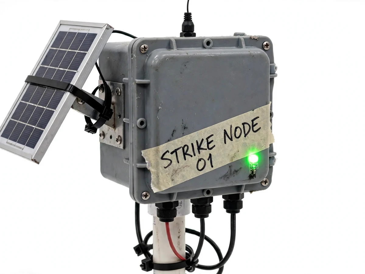
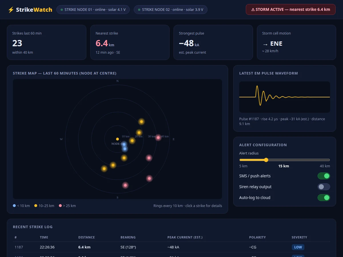
Lightning remains one of the biggest weather killers, and the people most at risk — farmers, construction crews, school playgrounds, outdoor event crowds — rarely get a timely local warning. Professional lightning-location networks exist, but their data is commercial and far beyond a student or community budget. This project closes that gap with a buildable IoT alternative: a dedicated lightning sensor IC listens for the electromagnetic pulse of each discharge, rejects man-made disturbers, and reports the strike's estimated distance; an ESP32 timestamps each event and publishes it over Wi-Fi; and a web dashboard turns the stream into a live strike map with range rings, a waveform view of the latest pulse, and an alert engine that messages you when strikes close in. A solar panel and battery keep the node running in the field, and a siren-relay output can sound a local hooter.
How it works
- The sensor continuously listens for lightning EM pulses; on a validated strike it interrupts the ESP32 with distance and energy estimates.
- The ESP32 timestamps the event and publishes it over Wi-Fi (MQTT/HTTP), with store-and-forward across outages.
- The backend appends the event to the strike log and pushes it to the dashboard over a live channel.
- The dashboard plots the strike on the range-ring map, updates the nearest-strike and storm-status cards, and refreshes the waveform view.
- The alert engine compares each strike's distance against the configured radius and sends SMS/push alerts for in-radius strikes.
- The siren relay output can drive a local hooter; everything keeps running on solar + battery between charges.
Tech stack:
- ESP32 (node controller + Wi-Fi)
- AS3935-class lightning sensor with antenna
- MQTT · Wi-Fi telemetry
- Solar panel + Li-ion + charge controller
- Node.js backend with event store
- HTML · CSS · JS dashboard
- SMS · push alert gateway
- Weatherproof enclosure + pole mount
| Parameter | Value |
|---|---|
| Detection | Lightning EM pulses, sensor-validated |
| Distance estimate | Sensor-provided per strike (approximate) |
| Alert radius | 5–40 km, user configurable |
| Dashboard | Live map, event log, waveform, alert config |
| Telemetry | MQTT/HTTP over Wi-Fi with store-and-forward |
| Power | Solar + Li-ion battery (design target: multi-day autonomy) |
| Enclosure | Weatherproof, pole-mounted |
| Siren output | Relay contact for external hooter |
| Alert channels | SMS / push via gateway account |
| Range | Single-node coverage (design target, site-dependent) |
Project features
- [Lightning EM-pulse sensing] Dedicated sensor IC (AS3935-class) with tuned antenna, noise-floor calibration and disturber rejection.
- [Strike distance estimation] Per-event distance estimate from the sensor, plotted on the dashboard's range-ring map.
- [Live strike map] Range rings every 10 km around the node, strikes colour-coded by distance band, click a strike for details.
- [Storm alert engine] Configurable alert radius (5–40 km); SMS/push alerts fire when strikes land inside it.
- [Pulse waveform view] The latest strike's EM waveform rendered on the dashboard with rise-time and peak-current estimates.
- [Solar field power] Panel plus Li-ion battery and charge controller in a weatherproof pole-mounted enclosure.
- [Siren relay output] Optional local hooter drive for sites where a phone alert isn't enough.
What is included
- Assembled lightning sensor node (ESP32, sensor, antenna, solar, battery, enclosure)
- Node firmware with sensor tuning and telemetry
- Web dashboard (strike map, log, waveform, alert configuration)
- Backend service with event store and alert rules engine
- Sensor calibration and installation guide
- Project report PDF (EM sensing theory, system design, methodology)
- PPT presentation and viva Q&A
Limitations & prerequisites
- Strike distances are the sensor IC's own estimates — approximate by nature, not surveyed positions; single-node bearing is not resolved.
- Detection range is a design target and varies with terrain, antenna placement and storm intensity.
- SMS/push alerts need a gateway account and mobile coverage at the user's end.
- The system is an educational early-warning aid, not a substitute for official meteorological warnings.
- Wi-Fi coverage is required at the node site; a LoRa variant is future scope.
Frequently Asked Questions
How does it detect lightning?
A dedicated sensor IC listens for the specific electromagnetic signature of a lightning discharge — rise time, energy profile — and rejects man-made disturbers like motors and switches through spike-rejection tuning.
How accurate is the distance estimate?
It is the sensor's own estimate based on signal energy, good enough to colour-code strikes into distance bands on the map. True triangulation needs multiple nodes, listed as future scope.
What happens when a storm approaches?
Strikes appear on the live map in real time; when one lands inside your configured alert radius, you get an SMS/push alert, and the optional siren relay can sound a local hooter.
Can it run off-grid?
The node is solar-powered with battery backup for multi-day autonomy (design target), but it still needs Wi-Fi at the site to stream events.
Is it safe to install?
The node is a low-voltage sensing device in a weatherproof enclosure; it does not attract lightning and must be mounted per the installation guide, away from tall conductive structures' strike zones.
Is this project suitable for a final-year project?
Yes — for Electronics, Electrical and IoT programs. It combines analog sensing, embedded firmware, wireless telemetry and a full web dashboard in one coherent system. Suitable for B.E./B.Tech final-year projects in Electronics, Electrical and IoT.
Components & software requirements
- ESP32 (node controller + Wi-Fi)
- AS3935-class lightning sensor with antenna
- MQTT · Wi-Fi telemetry
- Solar panel + Li-ion + charge controller
- Node.js backend with event store
- HTML · CSS · JS dashboard
- SMS · push alert gateway
- Weatherproof enclosure + pole mount
Delivery information
Built-to-order project. Delivery timeline is shared after order confirmation based on current queue.
Support terms
Complete documentation, setup guide, and viva preparation included. Support for setup and explanation provided.