
More project photos (2)
The problem
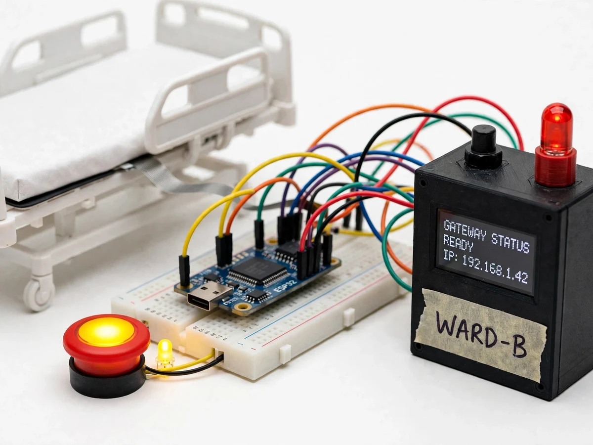
In a busy ward, nurses learn about a waiting patient only when someone walks the corridor — call bells exist, but most demo-grade nurse-call setups are just a buzzer with no record of which bed called, when, or how long the response took. That missing record is exactly what a student build can demonstrate: per-bed occupancy sensing, addressed call buttons, response-time logging and a live ward map. This project implements it with ESP32 bed nodes at demo scale: a pressure mat under each demo bed senses occupancy, a call button with an acknowledgement LED lets the "patient" call, and nodes report over ESP-NOW to a central gateway that drives the nurse-station dashboard. The dashboard shows the ward map with live bed states, running response timers for active calls and occupancy statistics. The build is explicit about its boundary: it demonstrates ward telemetry architecture and is not a medical device, carries no patient data and makes no clinical claims.
How it works
- Each bed node continuously reads its pressure mat for occupancy and watches its call button; state changes are debounced in firmware.
- On a call press, the node lights its local LED, starts its local timer and transmits a call packet (bed ID, timestamp) to the gateway over ESP-NOW.
- The gateway receives the packet, sounds the nurse-station buzzer, lights the tower LED and forwards the event over Wi-Fi to the dashboard.
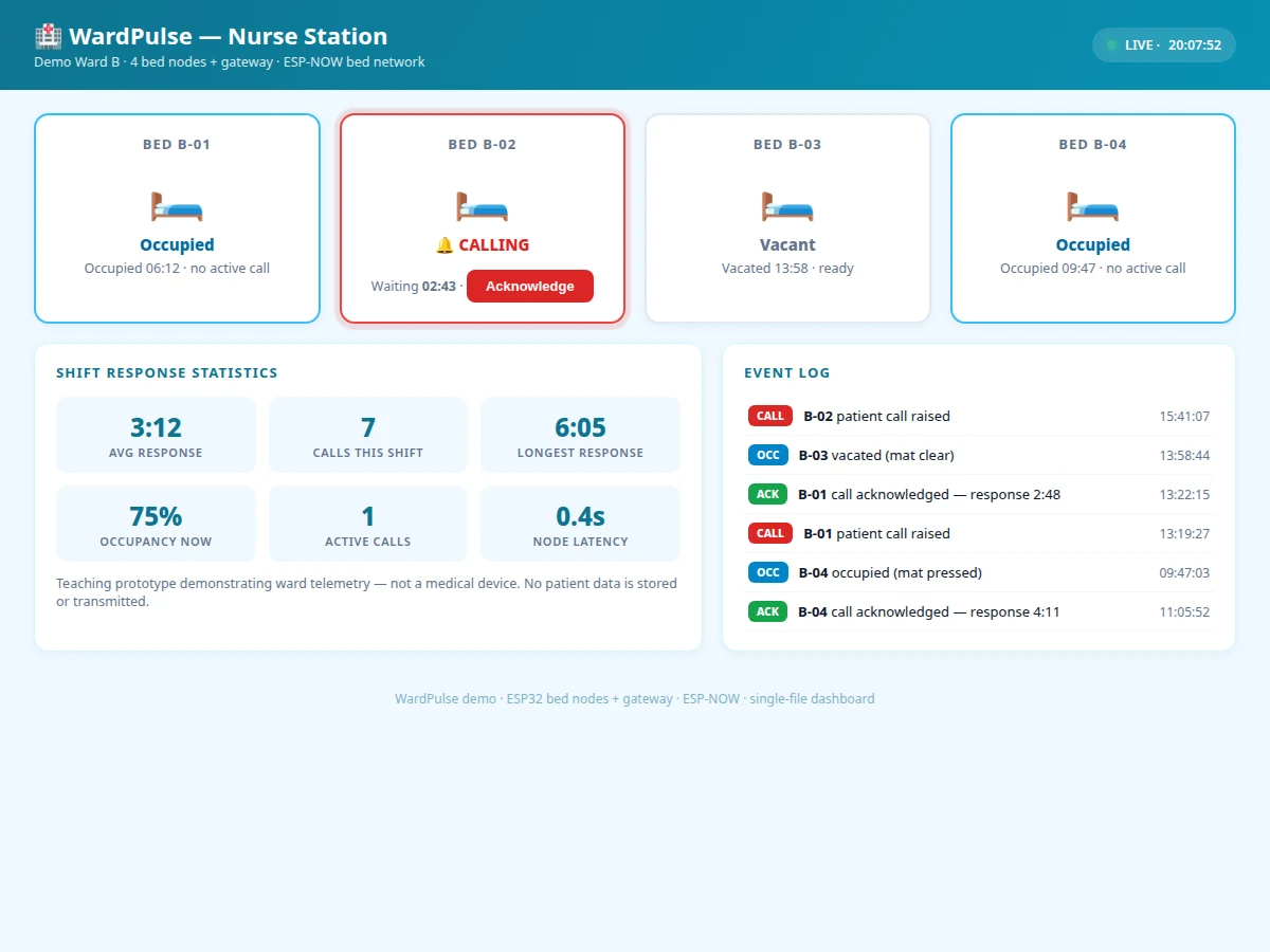
- The dashboard marks the bed tile as calling and starts the visible response timer; occupancy tiles update live as mats change state.
- The nurse acknowledges the call from the dashboard or gateway button; the acknowledgement packet returns to the bed node and clears its LED.
- All events — occupancy changes, calls, acknowledgements — are timestamped in the dashboard log, feeding the response-time statistics.
Tech stack:
- ESP32 bed nodes + central gateway (ESP-NOW + Wi-Fi)
- Pressure mats (occupancy) per bed
- Call buttons with acknowledgement LEDs
- Buzzer + tower LED + OLED (nurse station)
- MQTT/HTTP telemetry to dashboard
- HTML/CSS/JS ward dashboard
- Arduino IDE (C/C++ firmware)
| Parameter | Value |
|---|---|
| Demo scale | 4 bed nodes + 1 gateway (standard build) |
| Bed network | ESP-NOW, approximately <100 ms typical latency (design target) |
| Occupancy sensing | Pressure mat, occupied/vacant threshold calibrated per mat |
| Call latency | Button press to dashboard tile under 1 s (design target) |
| Dashboard | Single-file web app; ward map, timers, statistics |
| Gateway uplink | Wi-Fi MQTT/HTTP to dashboard |
| Power | 5 V adapters (bed nodes and gateway) |
Project features
- [Per-bed occupancy sensing] Pressure mats under each demo bed report occupied/vacant state, so the ward map always reflects the true bed picture.
- [Addressed patient-call buttons] Each bed has a call button with a local LED; pressing it raises a bed-specific call on the dashboard and starts a response timer.
- [Response-time logging] Every call records raised-at and acknowledged-at timestamps, and the dashboard reports average and longest response times per shift.
- [Live ward map dashboard] A ward layout with per-bed status tiles (vacant, occupied, calling), running call timers and occupancy statistics in one view.
- [ESP-NOW bed network] Bed nodes report to the gateway over ESP-NOW — no Wi-Fi credentials per node, low latency and simple pairing.
- [Nurse-station alert] The gateway sounds a buzzer and lights a tower LED on any new call, with the calling bed shown on its local OLED.
- [Call acknowledgement flow] The nurse acknowledges from the dashboard (or a gateway button), which clears the bed LED and stops the timer — demonstrating a complete event lifecycle.
What is included
- Working hardware prototype (4 demo bed nodes with mats and call buttons + gateway station)
- ESP32 firmware for bed nodes (debounce, ESP-NOW) and gateway (alerts, forwarding)
- Companion dashboard demo (single-file HTML ward dashboard)
- Ward layout configuration guide (mapping bed IDs to the demo floor plan)
- Wiring diagram and node enclosure notes
- Project report PDF (background, ward telemetry concepts, architecture, methodology)
- PPT presentation for final review
- Viva Q&A preparation document (ESP-NOW, debouncing, event lifecycles, non-medical scope)
Limitations & prerequisites
- This is a teaching prototype demonstrating ward telemetry — it is not a medical device, carries no patient data and must never be presented as clinical equipment.
- Pressure mats sense presence, not identity or posture; a bag on the bed reads as occupied, which the report documents honestly.
- ESP-NOW range suits a demo ward (tens of metres); a real hospital floor would need planned infrastructure, which is outside the build.
- Response-time statistics measure the demo workflow only; they say nothing about care quality.
- The demo uses 4 beds; scaling to a full ward needs addressing, power planning and enclosure work listed as future scope.
- Call buttons are wired to the bed node — wireless patient pendants are a possible extension, not part of this build.
Frequently Asked Questions
How does the nurse know which bed is calling?
Every bed node has a unique ID. A call packet carries that ID, so the dashboard lights the exact bed tile on the ward map, the gateway OLED names the bed, and the response timer runs against that bed specifically.
Why ESP-NOW instead of Wi-Fi for the bed nodes?
Bed nodes only need to talk to one gateway, metres away. ESP-NOW gives low-latency peer-to-peer packets without per-node Wi-Fi credentials or a router dependency — simpler, faster and a good viva discussion on protocol choice.
What happens when the call is acknowledged?
The acknowledgement — from the dashboard or the gateway button — sends a packet back to the bed node, clears its LED, stops the response timer and logs both timestamps. The full event lifecycle is visible in the dashboard log.
How is occupancy actually sensed?
A pressure mat under each demo mattress changes resistance under weight; the firmware thresholds it to occupied/vacant with debouncing. The threshold is calibrated per mat during setup using the included procedure.
Could this be used in a real hospital?
No — and the report says so explicitly. Real nurse-call systems are certified medical devices with redundancy and regulatory approval. This build demonstrates the telemetry architecture for learning, nothing more.
Is this project suitable for a final-year project?
Yes — for Electronics, IoT and Embedded Systems programs. It combines multi-node wireless design, event-driven firmware and a genuinely useful dashboard, with an honestly stated scope. Suitable for B.E./B.Tech final-year projects in Electronics, IoT and Embedded Systems.
Components & software requirements
- ESP32 bed nodes + central gateway (ESP-NOW + Wi-Fi)
- Pressure mats (occupancy) per bed
- Call buttons with acknowledgement LEDs
- Buzzer + tower LED + OLED (nurse station)
- MQTT/HTTP telemetry to dashboard
- HTML/CSS/JS ward dashboard
- Arduino IDE (C/C++ firmware)
Delivery information
Built-to-order project. Delivery timeline is shared after order confirmation based on current queue.
Support terms
Complete documentation, setup guide, and viva preparation included. Support for setup and explanation provided.