
More project photos (2)
The problem
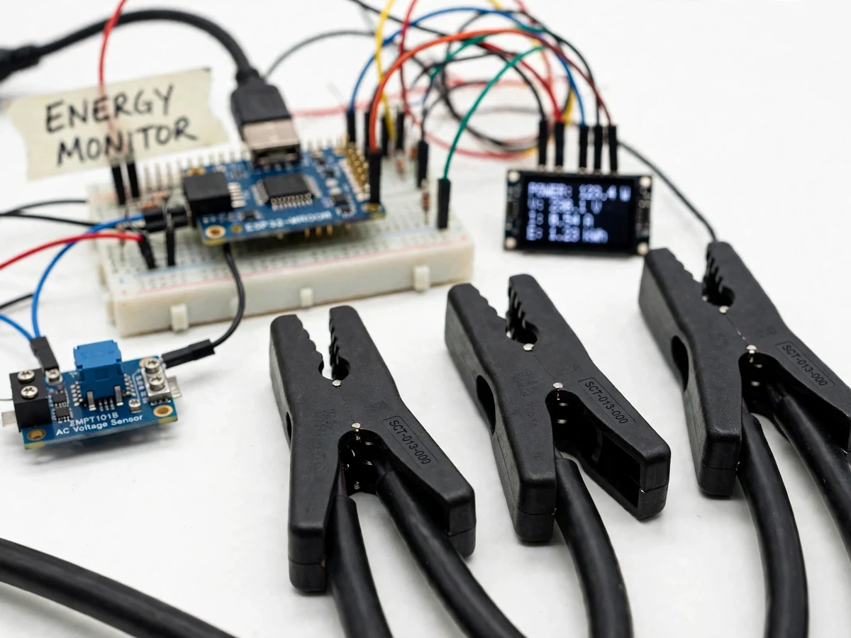
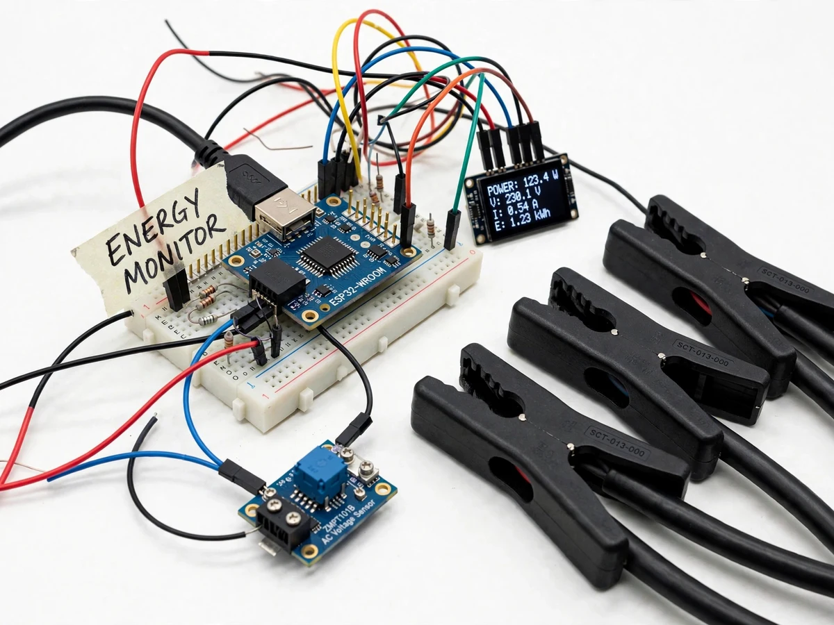
Most households discover their electricity bill only once a month, as a single number with no breakdown — so nobody knows whether the geyser, the air-conditioner or the old refrigerator is the real culprit. Utility smart meters are rolling out slowly and give the distribution company data, not the homeowner. This project puts the measurement in the student's hands: split-core CT clamps snap around the mains and up to four individual circuit wires without cutting anything, a ZMPT101B-class module senses the mains voltage, and an ESP32 computes real power, power factor and cumulative energy. Readings publish over Wi-Fi to a cloud dashboard with live gauges and history charts, and the student configures daily budgets that trigger phone alerts. The engineering spans analog sensing, RMS math on a microcontroller, and an end-to-end IoT telemetry pipeline.
How it works
- Split-core CT clamps are snapped around the mains incomer and up to four branch circuits; the voltage-sense module connects across the mains.
- The ESP32 samples the voltage and current waveforms, applies the calibrated burden and phase constants, and computes RMS voltage/current, real power, apparent power and power factor per channel.
- Energy is accumulated in non-volatile counters so totals survive power cuts and reboots.
- Every few seconds the node publishes the readings over Wi-Fi to the cloud dashboard; a heartbeat keeps the device-online status fresh.
- The dashboard renders live gauges, per-circuit power bars, and daily/weekly/monthly energy charts with tariff-based cost estimates.
- When a configured budget or per-appliance threshold is crossed, the cloud service sends an alert to the student's phone.
- The student calibrates each channel once against a known load (e.g. a 100 W bulb) using the included procedure, and the constants are stored in firmware.
Tech stack:
- ESP32 development board (Wi-Fi)
- SCT-013-class split-core CT clamps (mains + 4 circuits)
- ZMPT101B-class AC voltage sensing module
- Burden resistors + bias conditioning per channel
- 0.96-inch OLED display
- Cloud dashboard (ThingSpeak/Blynk class, MQTT/HTTP)
- Arduino IDE (C/C++ firmware)
- Tariff-based cost estimation on the dashboard
| Parameter | Value |
|---|---|
| Channels | 1 mains + 4 branch circuits (design) |
| Current range | 0–100 A per CT (datasheet, selected SCT-013 class) |
| CT accuracy | Approximately ±1–3% after buyer-run calibration (datasheet + procedure) |
| Voltage sensing | 230 V AC nominal via isolated module (design) |
| Computed quantities | Vrms, Irms, real/apparent power, power factor, kWh |
| Publish interval | Approximately every 5 s + heartbeat (design target) |
| Energy retention | Non-volatile counters, survive reboot (design) |
| Display | OLED: live mains power + today's energy |
Project features
- [Non-invasive CT sensing] Split-core SCT-013-class clamps snap around live conductors without cutting wires, so the monitor installs on a real home distribution board safely and reversibly.
- [Mains + 4 circuit channels] One CT on the mains plus four on individual appliance circuits enables appliance-level tracking — the student can see the geyser's 2 kW signature separately from the baseload.
- [True power computation] The ESP32 samples voltage and current waveforms together and computes real power, apparent power and power factor — not just current — with burden-resistor and calibration constants documented.
- [Live cloud dashboard] Power, voltage, current and power factor stream over Wi-Fi (MQTT/HTTP) to a dashboard with live gauges and daily/weekly/monthly energy charts.
- [Cost estimation] The student enters their tariff slab and the dashboard converts energy into rupee estimates per circuit and for the whole home.
- [Usage alerts] Daily budget and per-appliance power thresholds trigger phone/push alerts when consumption crosses the set limits.
- [On-device display] A small OLED shows live mains power and today's energy at the distribution board without opening the app.
What is included
- ESP32 energy-monitor node with CT inputs and OLED
- Set of split-core CT clamps + voltage sensing module
- Firmware with RMS/power computation and Wi-Fi telemetry
- Cloud dashboard setup guide with charts and tariff configuration
- Buyer-run per-channel calibration procedure (known-load method)
- Project report PDF (CT theory, power math, methodology)
- PPT presentation for final review
- Viva Q&A preparation document (CTs, real vs apparent power, power factor, IoT pipeline)
Limitations & prerequisites
- Current readings are only as good as the calibration: each channel must be calibrated against a known load by the student; uncalibrated error can reach several percent.
- Split-core CTs measure AC current only and need the conductor centered in the core for best accuracy.
- Appliance-level tracking covers the wired circuits only — it does not identify individual devices on a shared circuit (no NILM disaggregation in this build).
- Power factor is computed from the sampled waveforms; heavily distorted loads (cheap SMPS) reduce its precision.
- The monitor needs continuous Wi-Fi for live data; readings are buffered only briefly during outages.
Frequently Asked Questions
Do I need to cut any wires to install it?
No. Split-core CT clamps open, snap around the insulated conductor and close — fully non-invasive and reversible on a home distribution board.
How does it track individual appliances?
One CT goes on the mains and up to four on dedicated appliance circuits (geyser, AC, washing machine). Each channel's power and energy are computed and shown separately on the dashboard.
How accurate are the readings?
The selected CT class is rated around ±1–3% after calibration; the included known-load procedure lets you calibrate every channel yourself and document the result.
What does the dashboard show?
Live power/voltage/current/power-factor gauges, per-circuit power bars, daily/weekly/monthly energy charts, tariff-based cost estimates and the alert history.
What happens during a Wi-Fi outage?
Energy totals keep accumulating in non-volatile memory on the ESP32; live streaming resumes when Wi-Fi returns (short gaps are not backfilled in this build).
Is this project suitable for a final-year project?
Yes — for IoT, Embedded, Electrical and Electronics programs. It combines analog sensing, real-power computation on a microcontroller and a full cloud telemetry pipeline. Suitable for B.E./B.Tech final-year projects in IoT, Embedded Systems, Electrical and Electronics engineering.
Components & software requirements
- ESP32 development board (Wi-Fi)
- SCT-013-class split-core CT clamps (mains + 4 circuits)
- ZMPT101B-class AC voltage sensing module
- Burden resistors + bias conditioning per channel
- 0.96-inch OLED display
- Cloud dashboard (ThingSpeak/Blynk class, MQTT/HTTP)
- Arduino IDE (C/C++ firmware)
- Tariff-based cost estimation on the dashboard
Delivery information
Built-to-order project. Delivery timeline is shared after order confirmation based on current queue.
Support terms
Complete documentation, setup guide, and viva preparation included. Support for setup and explanation provided.