
More project photos (2)

The problem
Elderly people living alone face a quiet, serious risk: a fall nobody witnesses. A hip fracture or head injury can leave a person unable to reach a phone, and the hours spent waiting for help often decide how well they recover. Families worry, but round-the-clock supervision is neither affordable nor welcome — nobody wants a camera in a parent's bedroom. Commercial fall detectors exist, yet they are expensive, subscription-locked and opaque about how detection works. A student-built system must solve the same hard problems honestly: telling a real fall apart from sitting down hard, dropping the device or bending over, and raising an alert without depending on home WiFi. This project does that with a wrist-worn ESP32 and MPU6050 IMU, implementing the classic three-stage fall signature — free-fall dip, impact spike, post-fall inactivity — plus a cancel button so false alarms never needlessly panic the family.
How it works
- The MPU6050 continuously samples acceleration and angular velocity at 100 Hz; the ESP32 computes the resultant acceleration vector magnitude.
- A fall signature is flagged when the algorithm sees the three stages in sequence: a sudden free-fall dip (resultant < 0.6 g), a sharp impact spike (> 2.5 g) within ~1 second, then an inactivity window (minimal movement for ~10 seconds).
- On detection, the buzzer sounds and a 20-second cancel countdown starts on the device — if the wearer is fine, they press the red cancel button and nothing is sent.
- If the countdown expires, the GSM module (SIM800L) texts all registered emergency contacts with the fall time and a GPS location link.
- The event is logged with its timestamp and sensor trace for later review in the report.
Project features
- MPU6050 6-axis IMU (3-axis accelerometer + 3-axis gyroscope) in a wrist/belt-worn enclosure
- Three-stage fall signature: free-fall dip → impact spike → post-fall inactivity window
- Configurable sensitivity thresholds tuned for elderly movement profiles
- 20-second cancel countdown with buzzer — one button press stops false alarms
- GSM SMS alert to up to 5 emergency contacts with GPS location link
- On-device buzzer pre-alert sounds before the SMS goes out
- NEO-6M GPS module embeds a Google Maps link in the alert SMS
- Low-power design — ESP32 deep-sleep with motion-interrupt wake
- Activity log: fall events with timestamps stored on-device and viewable in the app
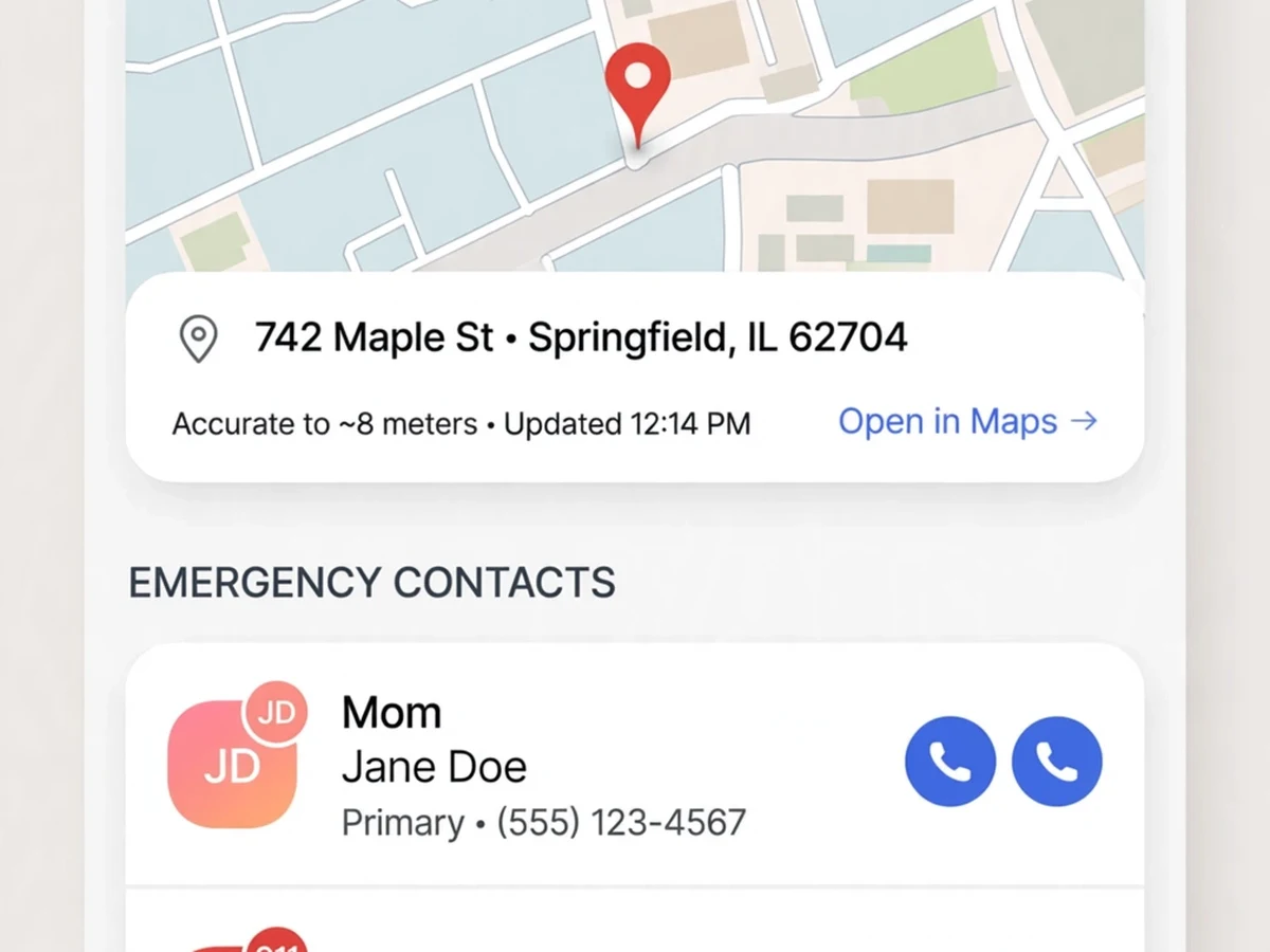
- Alert app view: fall-event notification card, location map and emergency contact list
What is included
- Fully assembled fall-detector wearable
- Complete firmware source code (Arduino IDE, well-commented)
- Circuit diagram and wiring schematic
- Fall-algorithm tuning guide (threshold explanation for the viva)
- Project report PDF (synopsis, design, test procedure, conclusion)
- PPT presentation for final review
- Viva Q&A preparation document
- GSM SIM setup and contact-registration guide
FAQs
- How accurate is the fall detection? The three-stage signature (free-fall → impact → inactivity) rejects most everyday motions like sitting or bending. Design target is ~90%+ sensitivity on simulated falls once thresholds are tuned; the report documents the evaluation procedure and the false-alarm cases to watch for.
- What stops false alarms from alerting my family? The 20-second buzzer countdown. Every detection first warns the wearer; a single press of the red button cancels the alert. The SMS only goes out if nobody cancels.
- Does it need the internet? No — alerts go over the GSM cellular network as SMS, so it works anywhere with mobile signal, even without WiFi or a paired smartphone.
- How long does the battery last? The ESP32 sleeps in deep-sleep mode and wakes on motion interrupts, giving roughly 2–3 days per charge on an 18650 cell. The report includes the full power-budget table.
- Can I demo this safely? Yes — drop the device onto a cushion or simulate the motion profile; the buzzer countdown and (test-mode) SMS fire exactly as in a real fall. A safe demo script is included.
- How can I extend this project? Common extensions include: heart-rate (MAX30102) anomaly fusion, LoRa instead of GSM for campus-scale coverage, fall-direction classification, and a caregiver cloud dashboard with history.
Limitations & prerequisites
- This is an engineering prototype, not a certified medical device — a fall alert aid, not a diagnostic tool.
- GPS needs a clear view of the sky; indoors, the alert goes out without a location link.
- A working SIM card with SMS balance and network coverage is required for alerts.
- Vigorous activities (dropping the device, sudden sitting) can trigger false detections — the cancel button is the designed safeguard.
Components & software requirements
- ESP32 DevKit microcontroller (WiFi + Bluetooth, dual-core 240 MHz)
- MPU6050 6-axis IMU (±16 g accel, ±2000 °/s gyro, I2C)
- SIM800L GSM module (SMS alerts, quad-band)
- NEO-6M GPS module (location link in alerts)
- Active buzzer + red cancel push-button
- 18650 Li-ion battery + TP4056 charger module
- Wearable wrist/belt enclosure, connecting wires
- Alert app view (fall notifications, map, contact list)
Specifications
| Parameter | Value |
|---|---|
| Microcontroller | ESP32 (240 MHz dual-core) |
| IMU | MPU6050, 100 Hz sampling, I2C interface |
| Fall stages | Free-fall < 0.6 g → impact > 2.5 g → 10 s inactivity |
| Cancel window | 20 s with buzzer countdown |
| Alert channel | SMS via SIM800L (up to 5 contacts) |
| Location | NEO-6M GPS, Google Maps link in SMS |
| Alert latency | < 60 s from impact to SMS delivery |
| Battery | 18650 Li-ion, ~2–3 days per charge, estimated (deep-sleep) |
| Enclosure | Wrist/belt-worn, button reachable with one hand |