
More project photos (2)
The problem
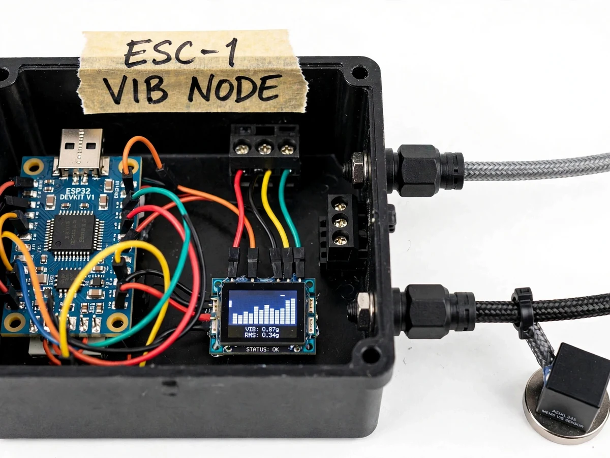
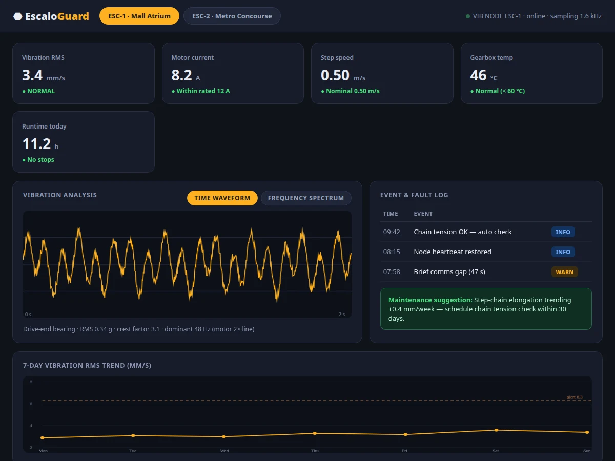
Escalators in malls and metro stations run 12–18 hours a day, and their failures are disruptive and occasionally dangerous — step-chain elongation, bearing wear and drive faults develop silently until a breakdown or an emergency stop. Maintenance today is mostly schedule-based: technicians inspect at fixed intervals whether the machine needs it or not. Vibration is the earliest tell — a degrading bearing or loosening chain changes the machine's vibration signature weeks before failure. This project builds the instrument that watches for it: a wireless ESP32 node with a magnet-mounted MEMS accelerometer at the drive-end bearing, plus motor current, step speed and gearbox temperature sensing, streaming to a dashboard that renders waveform and spectrum views, trends vibration RMS over 7 days, logs events, and suggests the right maintenance check in plain language. Strictly monitoring-only: nothing in this build can command the escalator.
How it works
- The accelerometer is magnet-mounted at the drive-end bearing; current, speed and temperature sensors are fitted at the drive.
- The ESP32 samples vibration at ~1.6 kHz, computing RMS, crest factor and dominant frequency per window, shown live on the OLED.
- Feature sets plus current, speed and temperature are published over Wi-Fi to the backend with timestamps.
- The dashboard renders live gauges, the waveform/spectrum view, the 7-day RMS trend and the event log.
- Threshold and trend rules watch the data: RMS crossing the alert line or a rising elongation trend raises a fault event.
- Each fault event carries a maintenance suggestion; the node itself only observes and never drives the escalator.
Tech stack:
- ESP32 (node controller + Wi-Fi)
- ADXL345-class MEMS accelerometer, magnetic mount
- Current · speed · temperature sensors
- 0.96" OLED on-node display
- Wi-Fi telemetry with timestamps
- Vibration feature extraction (RMS · crest factor · FFT)
- HTML · CSS · JS dashboard
- Threshold + trend alert rules engine
| Parameter | Value |
|---|---|
| Vibration sampling | ~1.6 kHz (design target) |
| Features | RMS, crest factor, dominant frequency |
| Extra channels | Motor current, step speed, gearbox temp |
| Alert threshold | Vibration RMS 6.3 mm/s (configurable, design target) |
| Trend window | 7-day RMS history |
| Dashboard | Gauges, waveform/spectrum, trend, event log |
| On-node display | 0.96" OLED with live bar graph |
| Telemetry | Wi-Fi, timestamped feature sets |
| Mounting | Magnetic accelerometer base at drive-end bearing |
| Control interface | None — monitoring only, by design |
Project features
- [Vibration feature extraction] Tri-axial MEMS sensing with RMS, crest factor and dominant-frequency computed on the ESP32 at ~1.6 kHz sampling (design target).
- [Multi-channel monitoring] Motor current, step speed and gearbox temperature tracked alongside vibration for full context.
- [Waveform + spectrum views] Switchable time-waveform and frequency-spectrum plots of the latest vibration window on the dashboard.
- [7-day trend with alert line] Vibration RMS trended daily against a configurable alert threshold.
- [Event & fault log] Timestamped INFO/WARN events: comms gaps, heartbeat restores, threshold crossings.
- [Maintenance suggestions] Plain-language advisories from trend rules (e.g. chain-elongation trend → schedule tension check).
- [On-node OLED readout] Live vibration bar graph, RMS and status on the node's own display for field checks.
What is included
- Assembled sensor node (ESP32, accelerometer, OLED, sensor inputs, enclosure)
- Node firmware with vibration feature extraction and telemetry
- Web dashboard (gauges, waveform/spectrum, trend, event log, suggestions)
- Backend with data store and alert rules engine
- Installation and mounting notes
- Project report PDF (vibration theory, system design, methodology)
- PPT presentation and viva Q&A
Limitations & prerequisites
- Vibration thresholds and sampling figures are design targets; fault rules are heuristic advisories, not certified diagnostics.
- The system must never be wired into escalator safety circuits or the controller — monitoring only, stated throughout the documentation.
- Installation needs facility permission and a safe mounting point; the guide covers placement, not site certification.
- Wi-Fi coverage is required at the node; a LoRa/cellular variant is future scope.
- Bearing-fault frequency matching is future scope — the base build reports features and trends, not named fault diagnoses.
Frequently Asked Questions
What does vibration tell you about an escalator?
Bearings, chains and drives each have a vibration signature; rising RMS, a climbing crest factor or a new dominant frequency indicates developing wear weeks before it becomes a failure.
How is the sensor attached?
The MEMS accelerometer sits on a round magnetic base, mounted at the drive-end bearing — no drilling, removable for maintenance windows.
Can it stop the escalator on a fault?
No, and it must not. This is a monitoring-only instrument; all control stays with the escalator's own certified controller and safety circuits.
What is crest factor and why show it?
Peak-over-RMS ratio — it rises when impacts (like a spalled bearing) appear in the vibration, often before RMS itself climbs. The dashboard reports both.
Does it work on moving walkways too?
The sensing approach transfers directly; thresholds and mounting points would be re-tuned per machine, documented as an adaptation path.
Is this project suitable for a final-year project?
Yes — for Electronics, Electrical and IoT programs. It combines vibration analysis, embedded DSP, wireless telemetry and a genuinely useful dashboard. Suitable for B.E./B.Tech final-year projects in Electronics, Electrical and IoT.
Components & software requirements
- ESP32 (node controller + Wi-Fi)
- ADXL345-class MEMS accelerometer, magnetic mount
- Current · speed · temperature sensors
- 0.96" OLED on-node display
- Wi-Fi telemetry with timestamps
- Vibration feature extraction (RMS · crest factor · FFT)
- HTML · CSS · JS dashboard
- Threshold + trend alert rules engine
Delivery information
Built-to-order project. Delivery timeline is shared after order confirmation based on current queue.
Support terms
Complete documentation, setup guide, and viva preparation included. Support for setup and explanation provided.