
More project photos (2)
The problem
Elevators fail expensively — a seized bearing or a jammed door mechanism traps passengers and takes the car out of service for days. Yet most maintenance is still calendar-based: a technician visits every month whether the machine needs it or not. Predictive maintenance flips this around by watching the machine's own signals continuously. This project implements that idea on a tabletop elevator model: an MPU6050 vibration sensor on the car frame and a current sensor on the drive motor feed an ESP32, which learns the baseline vibration and current profile of a healthy trip. When vibration rises in a specific frequency band or motor current creeps upward — the classic signatures of bearing wear and mechanical drag — the system flags it on a cloud dashboard and pushes an alert, demonstrating condition-based maintenance on a real machine problem.
How it works
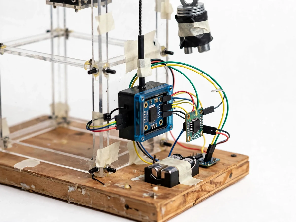
- The MPU6050 vibration sensor is mounted on the elevator car frame and the current sensor is placed in series with the drive motor supply.
- During commissioning, the elevator runs a set of healthy trips while the firmware records baseline vibration RMS and current profiles per trip phase (accelerate, cruise, decelerate).
- In normal operation, the ESP32 samples vibration and current on every trip and compares them against the stored baseline.
- Each door open/close cycle increments the door-cycle counter, which is tracked against the design maintenance interval.
- Readings publish over Wi-Fi to the cloud dashboard, where trend charts show vibration and current evolving over days of operation.
- When vibration RMS exceeds the warning band or current trends upward over successive trips, the system raises a WATCH/ALERT state and pushes a notification.
- The trip event log records every anomaly with timestamps, giving the report real trend data from the student's own test runs.
Tech stack:
- ESP32 (Wi-Fi microcontroller)
- MPU6050 vibration/IMU sensor
- ACS712 current sensor
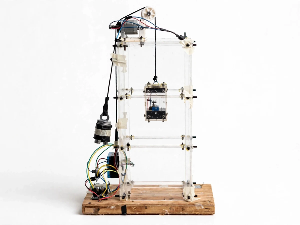
- Tabletop 3-floor elevator model
- MQTT broker + cloud dashboard
- Arduino IDE (C++ firmware)
- OLED status display
- 12 V DC drive supply
| Parameter | Value |
|---|---|
| Controller | ESP32 DevKit (dual-core, Wi-Fi) — datasheet |
| Vibration sensor | MPU6050, ±2g range typical use (datasheet) |
| Current sensor | ACS712 5 A variant (datasheet) |
| Elevator model | 3-floor tabletop rig, approximately 60 cm (prototype) |
| Sampling | Trip-phase profiles + continuous RMS (firmware) |
| Alert states | NORMAL / WATCH / ALERT with trend rules (implemented) |
| Dashboard | Trend charts + trip event log (MQTT) |
| Power | 12 V DC for drive, 5 V for node (design) |
Project features
- [Vibration signature monitoring] An MPU6050 on the car frame captures vibration during every trip; firmware compares RMS levels against the learned healthy baseline.
- [Motor current tracking] A current sensor on the drive motor watches for the slow current rise that signals bearing drag or misalignment — a leading indicator of mechanical trouble.
- [Door-cycle counting] Every door open/close is logged, since door mechanisms are the most frequent elevator failure point and cycle count drives their maintenance schedule.
- [Cloud trend dashboard] Vibration, current and cycle counts stream to the cloud with long-term trend charts — the heart of predictive maintenance is the trend, not the instant value.
- [Predictive alerts] Threshold-plus-trend rules raise EARLY WARNING before hard limits trip, with NORMAL / WATCH / ALERT states shown on the dashboard and a local display.
- [Trip event log] Each trip is logged with timestamp, floors served, vibration peak and current draw for the report's analysis section.
- [Baseline learning mode] A calibration routine records the healthy signature during commissioning; all later comparisons are relative to the student's own machine.
What is included
- Tabletop 3-floor elevator model with sensors fitted
- ESP32 health-monitoring node (assembled, programmed)
- Cloud trend dashboard setup with alert rules
- Complete firmware source code with baseline-learning routine
- Wiring diagram and sensor mounting guide
- Baseline commissioning procedure document
- Project report PDF (background, predictive-maintenance theory, firmware, results)
- PPT presentation for final review
- Viva Q&A preparation document (vibration analysis, current signature, MQTT)
Limitations & prerequisites
- This monitors a tabletop model; real elevators need certified sensors, safety-rated installation and compliance with lift codes — the report states this boundary plainly.
- Vibration baselines are machine-specific: the node must be recommissioned on any new machine, which the procedure document covers.
- The MPU6050 is a consumer IMU, not an industrial accelerometer; it detects trend changes well but is not a precision vibration-analysis instrument.
- Current-signature fault detection is trend-based; it flags developing problems but cannot diagnose the exact failed component.
- Wi-Fi is required for cloud trends and phone alerts; local display and logging continue offline.
- Simulated faults (added imbalance, drag load) are used to demonstrate detection — the report labels these as induced test conditions, not real failures.
Frequently Asked Questions
How can vibration predict a failure?
Healthy machines have a stable vibration signature. Bearing wear, looseness or misalignment raise vibration levels and change the profile before the machine actually fails — tracking the trend gives the warning weeks or months early. This is standard condition-monitoring practice.
What faults can the system actually detect?
Trend-level ones: rising vibration RMS (wear/looseness), rising motor current (drag/misalignment), and door-cycle count against service intervals. It flags developing problems; it does not name the exact failed part.
What is the baseline learning mode?
During commissioning the elevator runs healthy trips and the firmware records the normal vibration and current profile. Every later trip is compared against this stored baseline, so detection adapts to the specific machine.
How are faults demonstrated for the demo?
With safe, induced conditions — a small added imbalance weight, a light drag load on the drive — clearly labeled in the report as simulated test conditions that produce the same signature trends as real developing faults.
Can this be fitted to a real elevator?
The sensing principle is exactly what industry uses, but real lifts need certified hardware, safety-rated installation and lift-code compliance — all discussed as future scope. The prototype proves the pipeline end to end.
Is this project suitable for a final-year project?
Yes — for Electronics, Electrical and IoT programs. It combines sensor interfacing, signal trending, embedded firmware and a genuine industrial maintenance problem. Suitable for B.E./B.Tech final-year projects in Electronics, Electrical and IoT.
Components & software requirements
- ESP32 (Wi-Fi microcontroller)
- MPU6050 vibration/IMU sensor
- ACS712 current sensor
- Tabletop 3-floor elevator model
- MQTT broker + cloud dashboard
- Arduino IDE (C++ firmware)
- OLED status display
- 12 V DC drive supply
Delivery information
Built-to-order project. Delivery timeline is shared after order confirmation based on current queue.
Support terms
Complete documentation, setup guide, and viva preparation included. Support for setup and explanation provided.