
More project photos (2)
The problem
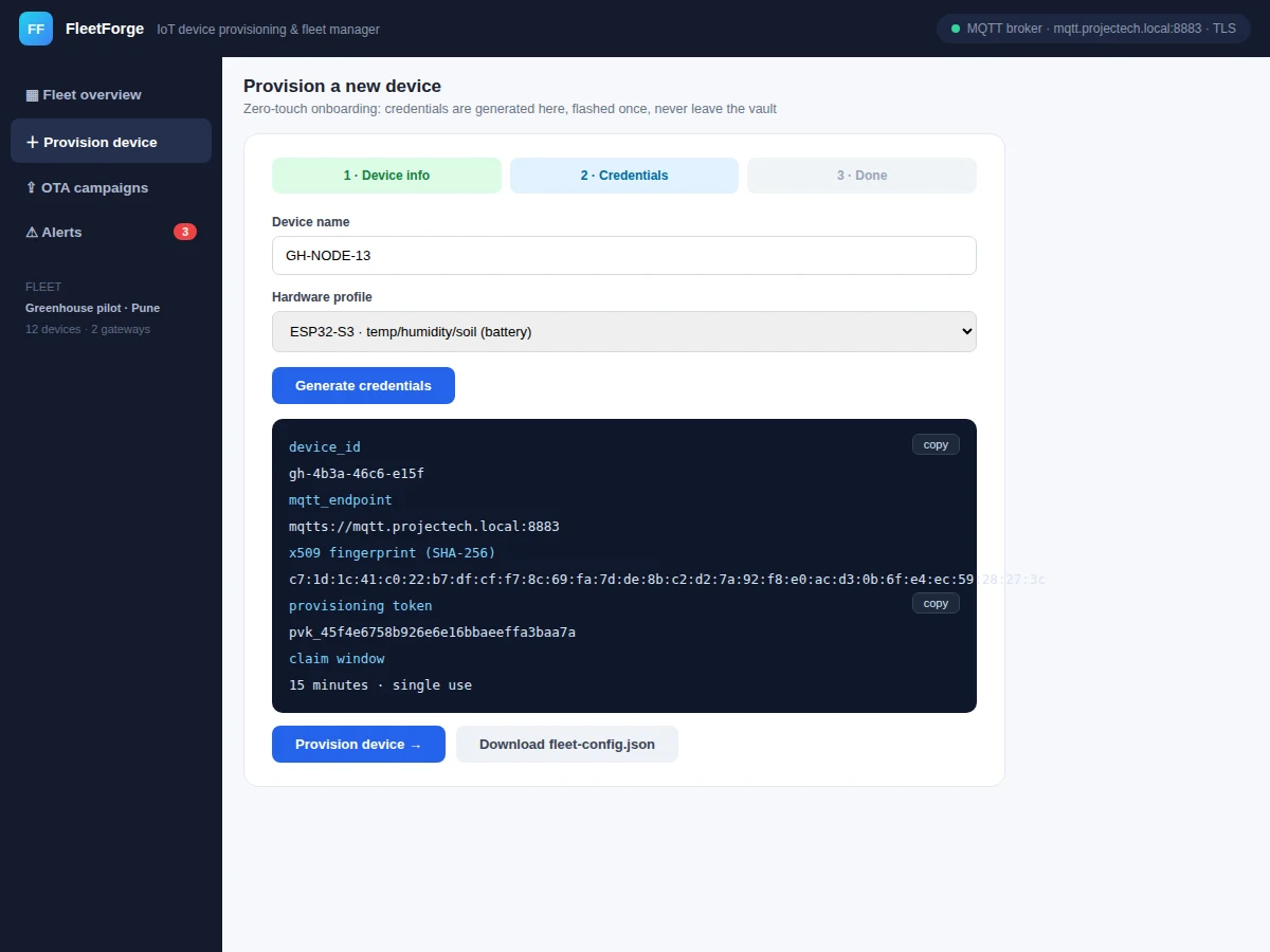
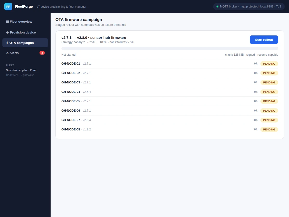
A single IoT prototype is easy; twenty of them in a greenhouse is a different problem. Each device needs unique credentials flashed securely, a way to know it is alive and healthy, firmware updates without a site visit, and alerts when something fails — the unglamorous operations work that decides whether a deployment survives. This project builds the operations console for that job. The provisioning wizard generates per-device identity (device ID, MQTT endpoint, X.509 certificate fingerprint, single-use provisioning token with a 15-minute claim window) and exports a fleet-config file for flashing. The fleet dashboard shows every device with live telemetry — temperature, humidity, soil moisture — plus battery, signal strength, firmware version and sparkline history, refreshing every two seconds. OTA campaigns roll firmware out in stages (canary → 25% → 100%) with per-device progress, automatic skip of offline nodes, and a failure threshold that halts the rollout. An alerts feed collects offline, low-battery, threshold-breach and stale-firmware events with timestamps.
How it works
- The operator starts the provisioning wizard, enters the device name and picks a hardware profile (ESP32-S3, ESP32-C3, Raspberry Pi gateway).
- The wizard generates a unique device ID, a 256-bit X.509 certificate fingerprint, an MQTT endpoint and a single-use provisioning token valid for 15 minutes.
- The fleet-config.json is downloaded and flashed to the device once; on first boot the device claims its identity and starts publishing telemetry.
- The dashboard subscribes to each device's telemetry topic (simulated live in the demo) and renders cards with sensor values, battery, RSSI and sparklines.
- For firmware updates, the operator creates an OTA campaign; devices move through canary, quarter and full phases with signed, resumable chunks.
- Each device reports download/install/reboot states; failures are counted against the halt threshold.
- Threshold rules (battery < 35%, soil < 25%, offline > 30 min, firmware behind) raise alerts into the feed automatically.
Tech stack:
- JavaScript (ES6) · HTML5 canvas sparklines
- MQTT over TLS (design)
- X.509 device identity (design)
- OTA state machine
- JSON fleet configuration
- Single-file web demo, zero dependencies
- Git
| Parameter | Value |
|---|---|
| Provisioning | Per-device ID + X.509 fingerprint + claim token (design target) |
| Claim window | 15 minutes, single use (design target) |
| Telemetry refresh | 2 s dashboard update (design target) |
| OTA strategy | Canary 2 → 25% → 100% (design target) |
| OTA chunk | 128 KiB, signed, resumable (design target) |
| Transport | MQTT over TLS, port 8883 (design target) |
| Demo fleet | 9 devices, greenhouse pilot scenario (design target) |
Project features
- [Zero-touch provisioning wizard] Three steps — device info, credential generation, done — producing a unique device ID, X.509 fingerprint and single-use claim token per device.
- [Live fleet dashboard] Every device card shows temperature, humidity, soil moisture, battery, signal bars, firmware version and a telemetry sparkline, updating every 2 seconds.
- [Staged OTA campaigns] Canary → 25% → 100% rollout with per-device states (pending, downloading, installing, rebooting, done), signed 128 KiB chunks and resume capability.
- [Automatic failure handling] Offline devices are marked failed instead of blocking the campaign; a failure threshold halts the rollout.
- [Alerts feed] Offline, low-battery, threshold-breach and stale-firmware alerts with severity levels and timestamps.
- [Fleet health cards] Devices online, 24-hour uptime, average battery and active alerts summarized at a glance.
- [fleet-config.json export] One-click export of the provisioned device's connection config for flashing.
- [MQTT/TLS status] Broker connection state visible in the header, documenting the secure transport design.
What is included
- Complete single-file fleet manager application
- Provisioning and OTA design documentation (identity flow, rollout state machine)
- fleet-config.json schema and flashing guide
- Project report PDF (background, IoT fleet concepts, security design, methodology)
- PPT presentation for final review
- Viva Q&A preparation document (provisioning, MQTT, TLS, OTA strategies, fleet ops)
Limitations & prerequisites
- The demo simulates the device fleet and broker in the browser — real MQTT broker integration and device firmware are documented as the extension path.
- Credentials are generated client-side in the demo; a production build needs a server-side vault/HSM, stated honestly in the report.
- Scale figures (hundreds of devices) are design targets; the demo models a 9-device pilot.
- OTA binary signing is described in the design doc; the demo simulates the rollout state machine.
Frequently Asked Questions
What does "provisioning" mean here?
Giving each device a unique, secure identity before it joins the fleet — device ID, certificate fingerprint and a one-time token — so no two devices share credentials and rogue devices can't impersonate real ones.
How do OTA updates work safely?
Firmware rolls out in stages (2 canary devices, then 25%, then all), each device reports its progress, offline devices are skipped rather than blocking, and too many failures halt the campaign automatically.
Does this need real hardware?
The demo simulates the fleet so the whole workflow is demonstrable anywhere; the design docs specify exactly how real ESP32 firmware and an MQTT broker plug in.
How are devices secured?
Per-device X.509 identity, MQTT over TLS, single-use claim tokens with a 15-minute window, and credentials generated once and never displayed again.
What alerts does it raise?
Device offline, low battery, sensor threshold breaches (e.g. soil moisture below irrigation level) and firmware falling behind the fleet — each with severity and timestamp.
Is this project suitable for a final-year project?
Yes — for IoT & Embedded, Computer Science and Electronics programs. It demonstrates IoT security, fleet operations, OTA design and full-stack dashboard engineering. Suitable for B.E./B.Tech final-year projects in IoT & Embedded, Computer Science and Electronics.
Components & software requirements
- JavaScript (ES6) · HTML5 canvas sparklines
- MQTT over TLS (design)
- X.509 device identity (design)
- OTA state machine
- JSON fleet configuration
- Single-file web demo, zero dependencies
- Git
Delivery information
Built-to-order project. Delivery timeline is shared after order confirmation based on current queue.
Support terms
Complete documentation, setup guide, and viva preparation included. Support for setup and explanation provided.