
More project photos (2)
The problem
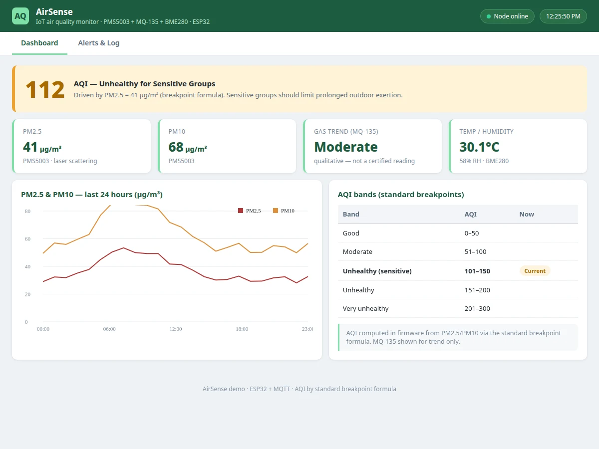
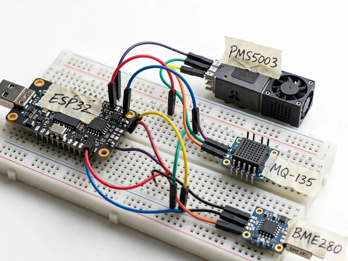
Cheap "air quality" gadgets usually report a single meaningless number from an uncalibrated gas sensor. This monitor is built differently. A PMS5003 laser-scattering sensor measures real PM2.5 and PM10 particle concentrations — the pollutants health agencies actually regulate — while an MQ-135 reports total gas/VOC trends and a BME280 provides temperature and humidity for context and compensation. An ESP32 computes the AQI from PM2.5/PM10 using the standard breakpoint formula, publishes readings over Wi-Fi via MQTT, and a dashboard renders live values, AQI gauge, 24-hour pollutant graphs and a color-coded health category. When the AQI crosses into unhealthy bands, a mobile push alert goes out with the measured values. The listing states sensor realities honestly: the PMS5003 is a real particle counter (not a guess), the MQ-135 is qualitative, and calibration means side-by-side comparison with a reference, not factory claims.
How it works
- The PMS5003's fan draws air through its laser chamber; scattered-light pulses are counted into PM1.0/PM2.5/PM10 concentrations.
- The ESP32 reads the MQ-135 (analog gas trend) and BME280 (temperature/humidity/pressure) alongside the particle data.
- Firmware computes the AQI from PM2.5 and PM10 using the standard breakpoint formula and assigns the health category.
- The readings are published over Wi-Fi via MQTT to the cloud backend at a configurable interval (design target: 60 s).
- The dashboard renders the live AQI gauge, pollutant trend graphs, 24-hour history and the health-category banner.
- When the AQI crosses a configured threshold, the alert service pushes a mobile notification with the measured values; thresholds and the MQ-135 burn-in procedure are part of the setup guide.
Tech stack:
- ESP32 development board
- PMS5003 laser PM2.5/PM10 sensor
- MQ-135 gas sensor (qualitative trend)
- BME280 temperature/humidity/pressure sensor
- MQTT broker + cloud dashboard (web)
- Mobile push alert service
- Arduino IDE (C/C++ firmware)
| Parameter | Value |
|---|---|
| Controller | ESP32, Wi-Fi telemetry via MQTT (JSON payloads) |
| PM sensing | PMS5003 laser scattering; PM1.0/PM2.5/PM10, fan intake |
| Gas sensing | MQ-135 analog, qualitative trend (not a certified concentration) |
| AQI | Computed from PM2.5/PM10 by standard breakpoint formula; color-coded categories |
| Dashboard | Live AQI gauge, pollutant graphs, 24-hour history, health banner |
| Alerts | Push notification on configurable AQI threshold crossing |
| Power | 5 V DC (PMS5003 fan + ESP32); USB or adapter |
Project features
- [Laser PM sensing] PMS5003 measures PM2.5 and PM10 by laser scattering — real particle counting, with fan-driven intake like reference-grade monitors.
- [Proper AQI computation] AQI is computed from PM2.5/PM10 using the standard breakpoint formula in firmware, with the standard color-coded health categories.
- [Gas trend sensing] MQ-135 reports total gas/VOC trends for context; presented honestly as qualitative, not as a certified gas concentration.
- [Environmental compensation] BME280 temperature, humidity and pressure readings accompany every sample for context and humidity-compensation reasoning.
- [Live dashboard] Current AQI gauge, pollutant graphs, 24-hour history and health-category banner, served as a working dashboard alongside the hardware.
- [Mobile push alerts] Configurable AQI thresholds (e.g. crossing into "Unhealthy") trigger push notifications carrying the measured PM values.
- [Burn-in and placement guidance] The deliverable documents the MQ-135 burn-in period and correct sensor placement — the practical details that make or break air sensing.
What is included
- Working air-quality node prototype (ESP32, PMS5003, MQ-135, BME280)
- Complete firmware source code (PM reading, AQI computation, MQTT telemetry, alert logic)
- Cloud pipeline + working dashboard (live AQI, graphs, alert log) demonstrated with the prototype
- Circuit and wiring documentation with burn-in and placement guidance
- Component list with ratings
- Buyer-run comparison procedure (side-by-side check against a reference station/app)
- Project report PDF (air-quality background, PM sensing and AQI theory, methodology, test procedure)
- PPT presentation for final review
- Viva Q&A preparation document (laser scattering, AQI formula, MQ-135 limits)
- Setup and demonstration guide
Limitations & prerequisites
- The MQ-135 is a qualitative gas-trend sensor, not a calibrated gas analyzer — it is presented as context, never as a certified concentration.
- The PMS5003 is a real particle counter but a consumer-grade one; readings should be compared side-by-side with a reference during the buyer's own check, not treated as regulatory data.
- Humidity affects optical particle readings; the BME280 data is provided for context, and the report documents the limitation honestly.
- The MQ-135 needs a documented burn-in period (design target: 24–48 h powered) before readings stabilize.
- Alerts need internet on the node and the phone; outages queue nothing.
Frequently Asked Questions
Which pollutants does it measure?
PM2.5 and PM10 by laser scattering (PMS5003), plus a qualitative gas/VOC trend (MQ-135) and temperature/humidity/pressure (BME280) for context.
How is the AQI computed?
From PM2.5 and PM10 using the standard breakpoint formula in firmware, with the standard color-coded health categories shown on the dashboard.
How accurate is it?
The PMS5003 counts real particles but is consumer-grade — the procedure has you compare it side-by-side with a reference station. The MQ-135 is qualitative only. No regulatory-grade claims are made.
How do the mobile alerts work?
When the computed AQI crosses your configured threshold, a push notification goes to the phone with the measured PM values. Both node and phone need internet.
What are the main limitations?
Qualitative gas sensing, humidity effects on optical readings, MQ-135 burn-in time, and internet-dependent alerts.
Is this project suitable for a final-year project?
Yes — for IoT and Embedded Systems programs. It covers real particle sensing, AQI computation, MQTT telemetry and honest sensor metrology, all strong viva material. Suitable for B.E./B.Tech final-year projects in IoT and Embedded Systems.
Components & software requirements
- ESP32 development board
- PMS5003 laser PM2.5/PM10 sensor
- MQ-135 gas sensor (qualitative trend)
- BME280 temperature/humidity/pressure sensor
- MQTT broker + cloud dashboard (web)
- Mobile push alert service
- Arduino IDE (C/C++ firmware)
Delivery information
Built-to-order project. Delivery timeline is shared after order confirmation based on current queue.
Support terms
Complete documentation, setup guide, and viva preparation included. Support for setup and explanation provided.