
More project photos (2)
The problem
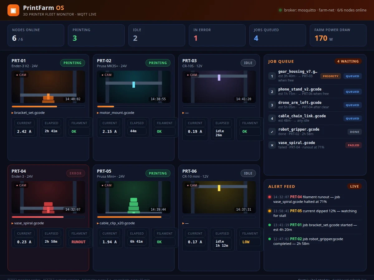
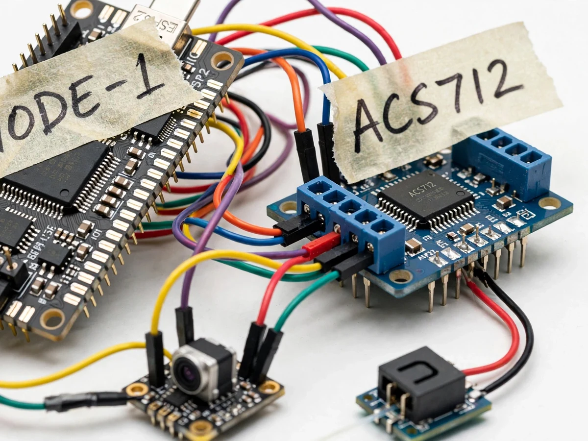
College makerspaces and small print farms often run three to ten 3D printers at once, and nobody can tell at a glance which machine is free, which one failed at 2 AM, or which is about to run out of filament. The usual answer is someone walking the room, checking screens and guessing — so failed prints waste hours and queued jobs sit idle while a printer stands free. This project gives the farm a nervous system: each printer gets a small ESP32 monitor node that reads the printer's DC supply current through an ACS712 Hall-effect sensor, watches a filament-runout switch, and snaps progress photos with an ESP32-CAM. The nodes publish over MQTT to a central dashboard that renders the whole farm as a live grid — printing, idle or error — alongside a shared job queue, a filament alert feed and job history. Because status is inferred from real power draw, no printer firmware changes are needed, so any 12/24 V DC machine can join the farm.
How it works
- The ACS712 sensor is wired in series with the printer's 12/24 V DC supply line (low-voltage side only — mains is never touched), and the monitor node runs on USB 5 V.
- At installation, firmware captures each printer's idle standby baseline, and the idle/printing/error current thresholds adapt to that baseline.
- The ESP32 samples current at approximately 1 kHz, computes RMS over a 1 s window and classifies the printer state; filament-switch changes fire an immediate MQTT alert message.
- Every 5 s the node publishes a JSON packet (current, state, filament, uptime) to farm/
/telemetry; retained messages keep the dashboard truthful on reload. - An ESP32-CAM grabs a snapshot every 10 min and on every alert (stills only — no video stream, keeping farm bandwidth low) for the printer's dashboard card.
- The single-file dashboard app connects to the broker over MQTT WebSockets and renders the farm grid, job queue and alert feed live in any browser on the local network.
- Operators queue jobs with estimated durations; progress bars advance from elapsed time, and jobs complete or flag failed when the node reports a state change.
Tech stack:
- ESP32 dev board · ACS712 5 A current sensor
- Optical filament runout switch
- ESP32-CAM snapshot module
- MQTT · Mosquitto broker
- Dashboard: HTML/CSS/JS · MQTT WebSockets
- Arduino IDE · C/C++ firmware
- 3D-printer 12/24 V DC interfacing
| Parameter | Value |
|---|---|
| Printers per coordinator | Up to 8 nodes (design target) |
| Current sensing | ACS712 5 A Hall-effect, ±1.5% typical (datasheet value) |
| Current sampling | Approx. 1 kHz sample rate, 5 s publish interval (design target) |
| State detection | Idle / printing / error from DC current signature |
| Runout alert latency | Within approx. 2 s of switch trigger (design target) |
| Camera | ESP32-CAM, still snapshot every 10 min + on alert (design target) |
| Connectivity | Wi-Fi, MQTT over local broker |
| Dashboard | Single-file web app, local-network browser access |
| Node supply | USB 5 V; sensing on 12/24 V DC side only |
| Queue capacity | 50 jobs with priority flag (design target) |
Project features
- [Current-signature state detection] ACS712 5 A Hall-effect sensor on the printer's DC input; the ESP32 samples current and a firmware state machine classifies each printer as idle, printing or error from its power signature — no printer firmware changes needed.
- [Filament-runout alerts] Optical runout switch per printer wired to the node; an MQTT alert fires within about 2 seconds (design target) of filament depletion, flagging the printer as ERROR on the dashboard.
- [Live farm grid dashboard] Every printer renders as a card with status, live current draw, filament state, elapsed time and progress bar — the whole farm readable in one glance.
- [Shared job queue] Operators add jobs (G-code filename, estimated duration, priority) and assign them to printers; the queue tracks pending, running, completed and failed states with a job history log.
- [Progress camera snapshots] ESP32-CAM captures a still every 10 minutes (design target) and on every alert; the latest snapshot appears on each printer card for quick visual checks.
- [MQTT telemetry backbone] Each node publishes JSON telemetry to a local Mosquitto broker every 5 seconds on its own topic; the dashboard subscribes over WebSockets so status updates land live.
- [Alert feed] Runout, error-state and node-offline events append to a timestamped alert feed — the farm's single incident log instead of word of mouth.
What is included
- Working monitor-node prototypes — 3 complete nodes (ESP32, ACS712, runout switch, ESP32-CAM), expandable to 8
- Complete node firmware source (current sampling, state machine, MQTT, alerts)
- Farm dashboard web app (live grid, job queue, alert feed, job history)
- Wiring diagrams and DC-side installation guide with safety notes
- MQTT topic map and Mosquitto broker setup guide
- Calibration procedure for idle-baseline thresholds
- Project report PDF (background, power-signature method, firmware design, MQTT architecture)
- PPT presentation for final review
- Viva Q&A preparation document (current sensing, state machines, MQTT, embedded power budgets)
Limitations & prerequisites
- Status is inferred from current draw, not the printer's firmware — a print paused from the screen reads as idle, and progress percentage is an elapsed-time estimate, not true layer tracking.
- The ±1.5% accuracy figure is the ACS712 datasheet typical, not a measured calibration result; the report documents the buyer-run calibration procedure instead.
- Monitoring is snapshot-based: stills every 10 min plus on alerts — there is no live video stream, by design, to keep farm bandwidth low.
- The dashboard is local-network only in this build; remote access needs a VPN or reverse proxy, listed as future scope.
- Mains voltage is never touched — the sensor sits on the low-voltage DC side only, so this node cannot detect mains-side failures.
- Stable Wi-Fi is required at the farm; nodes buffer only the last state locally and do not log long offline histories.
Frequently Asked Questions
How does it know a print failed instead of finishing?
The firmware watches the current signature: a mid-print drop to idle before the job's estimated duration elapses is flagged as an error/failed print, while a drop after the estimated time marks completion. The margin is tuned per printer during calibration.
Does it modify the printer or its firmware?
No. The node only observes — current sensing on the DC supply line, a runout switch in the filament path, and a camera pointed at the bed. The printer runs its stock firmware untouched.
Which printers does it support?
Any 12 V or 24 V DC machine whose supply current fits the ACS712 5 A range — that covers most desktop FDM printers. Mains-powered industrial machines are out of scope.
Can I see the farm from my phone?
The dashboard is a web app on the local network, so any phone or laptop on the same Wi-Fi sees the live grid, queue and alerts — no app install needed.
Is this project suitable for a final-year project?
Yes — for IoT & Embedded programs. It combines embedded current sensing, state-machine firmware design, MQTT networking and a real operational dashboard around a genuine makerspace problem. Suitable for B.E./B.Tech final-year projects in IoT & Embedded.
Components & software requirements
- ESP32 dev board · ACS712 5 A current sensor
- Optical filament runout switch
- ESP32-CAM snapshot module
- MQTT · Mosquitto broker
- Dashboard: HTML/CSS/JS · MQTT WebSockets
- Arduino IDE · C/C++ firmware
- 3D-printer 12/24 V DC interfacing
Delivery information
Built-to-order project. Delivery timeline is shared after order confirmation based on current queue.
Support terms
Complete documentation, setup guide, and viva preparation included. Support for setup and explanation provided.