
More project photos (2)

The problem
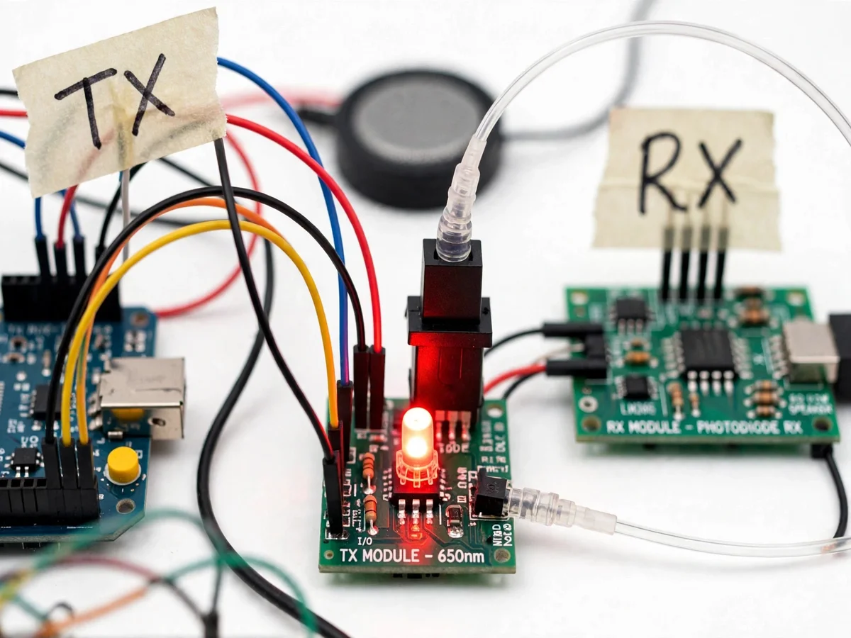
Optical fiber carries the world's data, yet most electronics students meet it only as a textbook diagram of total internal reflection. The engineering reality — coupling light into a fiber, modulating a source, recovering a weak optical signal at the far end, and proving the link ignores electrical noise — is never touched. This project closes that gap with a complete, working fiber-optic audio link built from student-friendly parts: a 650nm red LED transmitter module driven by an Arduino, a coil of plastic optical fiber, a photodiode receiver module, and an LM386 audio stage driving a small speaker. Speak or play audio into one end and hear it emerge from the other, carried entirely by light. The included comparison experiment runs the same audio over copper next to a noise source, making the electromagnetic immunity of fiber visible and audible rather than theoretical.
How it works
- Audio from a line-level source (or a firmware-generated test tone) is fed to the Arduino, which varies the drive current of the 650nm red LED in step with the signal.
- The LED's light is coupled into the plastic optical fiber through the transmitter's connector, entering the fiber core at an angle inside its acceptance cone.
- Light propagates along the fiber by total internal reflection at the core-cladding boundary, confined to the core for the whole run.
- At the receiver, the silicon photodiode converts the arriving optical power into a small photocurrent proportional to the light intensity.
- A transimpedance stage turns that photocurrent into a voltage, which the LM386 amplifier boosts to drive the speaker.
- For the noise-immunity demo, the same audio is also sent over an ordinary copper cable past a switching load, and the two outputs are compared.
Tech stack:
- Arduino Uno (ATmega328P)
- 650nm red LED transmitter module
- PMMA plastic optical fiber with connectors
- Silicon photodiode receiver module
- LM386 audio power amplifier
- C/C++ firmware (Arduino IDE)
- 5 V USB power bank supply
| Parameter | Value |
|---|---|
| Transmitter wavelength | 650 nm (red LED, datasheet value) |
| Fiber type | PMMA plastic optical fiber, approximately 1 mm core (typical) |
| Fiber length supplied | Approximately 10 m coil (design target) |
| Fiber attenuation | Approximately 0.2 dB/m at 650 nm (fiber datasheet typical) |
| Modulation | LED drive-current modulation from Arduino |
| Receiver | Silicon photodiode + transimpedance stage |
| Audio output | LM386 stage, approximately 0.3 W into 8 Ω (datasheet typical) |
| Supply | 5 V USB, 5000 mAh power bank supplied (expected) |
Project features
- [650nm optical transmitter] A red LED transmitter module modulated by the Arduino, with a fiber connector for direct coupling into the plastic optical fiber.
- [Plastic optical fiber channel] A coil of large-core PMMA fiber that is easy to terminate and align by hand — the right choice for a teaching link, with visible red light at the far end.
- [Photodiode receiver front-end] A silicon photodiode receiver module that converts the arriving optical power back into an electrical signal via a transimpedance stage.
- [LM386 speaker stage] The recovered audio is amplified by an LM386 power amplifier to drive the supplied speaker at comfortable listening volume.
- [Arduino modulation firmware] Firmware that modulates the LED drive current from a line-level audio source or a built-in test tone, with source code included for study.
- [EMI immunity demonstration] A guided experiment running the optical link and a copper cable side by side next to a switching noise source, showing the fiber's silence against the copper's hum.
- [Fiber coupling and alignment trial] A buyer-run procedure for seating and aligning the fiber in both connectors, so coupling efficiency is learned hands-on.
What is included
- 650nm TX module and photodiode RX module with LM386 speaker stage and speaker
- Plastic optical fiber coil with fitted connectors
- Arduino Uno with modulation firmware (full source included)
- Breadboard, jumper wires and 5000 mAh USB power bank
- Noise-immunity comparison procedure (optical vs copper)
- Project report PDF (fiber theory, modulation, link budget, measurements)
- PPT presentation for final review
- Viva Q&A preparation document (TIR, attenuation, modulation, EMI immunity)
Limitations & prerequisites
- Plastic fiber attenuation (approximately 0.2 dB/m typical) limits practical range; long runs need careful coupling or a brighter source.
- LED-to-fiber coupling efficiency depends on mechanical alignment, covered honestly by the buyer-run alignment procedure.
- Audio fidelity is demonstration-grade: LED nonlinearity and ambient light add distortion, so no hi-fi claim is made.
- An unshielded receiver picks up ambient-light flicker; the supplied hood/enclosure procedure mitigates it.
- No digital error correction is implemented — the link is a raw analog optical channel.
- Maximum usable range is a buyer-measured result of their own build, not a pre-claimed figure.
Frequently Asked Questions
How does audio travel as light?
The Arduino varies the current through the 650nm red LED in step with the audio waveform — brighter for peaks, dimmer for troughs. That intensity-modulated light travels the fiber, the photodiode converts brightness back into current, and the LM386 amplifies it to the speaker. It is analog amplitude modulation on an optical carrier.
Why plastic fiber instead of glass fiber?
Glass single-mode fiber needs precision cleaving, splicing and laser sources — impractical for a student bench. PMMA plastic fiber has a 1 mm core you can cut with a blade and align by hand, the red light is visible at the far end, and the physics (total internal reflection, attenuation, acceptance angle) is identical.
What do I actually measure for the report?
The buyer-run procedure covers received audio level versus fiber length (attenuation estimate), coupling loss with deliberate misalignment, and a noise-comparison recording of fiber versus copper next to a switching load. Every number in the report comes from the student's own bench.
Why is the fiber immune to electrical noise?
The signal travels as photons in a dielectric, not as current in a conductor, so there is nothing for electromagnetic fields to induce voltage on. The side-by-side experiment makes this audible: the copper cable hums near the noise source while the fiber stays silent.
Can it send digital data too?
The hardware path supports it — on-off keying of the LED is the same principle. The shipped firmware is analog-audio focused, and a digital UART-over-fiber extension is listed as future scope with the framing approach documented.
Is this project suitable for a final-year project?
Yes — for Electronics and Communication programs. It demonstrates optical communication end to end: modulation, fiber propagation, photodetection, amplification and a real noise-immunity measurement. Suitable for B.E./B.Tech final-year projects in Electronics and Communication Engineering.
Components & software requirements
- Arduino Uno (ATmega328P)
- 650nm red LED transmitter module
- PMMA plastic optical fiber with connectors
- Silicon photodiode receiver module
- LM386 audio power amplifier
- C/C++ firmware (Arduino IDE)
- 5 V USB power bank supply
Delivery information
Built-to-order project. Delivery timeline is shared after order confirmation based on current queue.
Support terms
Complete documentation, setup guide, and viva preparation included. Support for setup and explanation provided.