
More project photos (2)

The problem
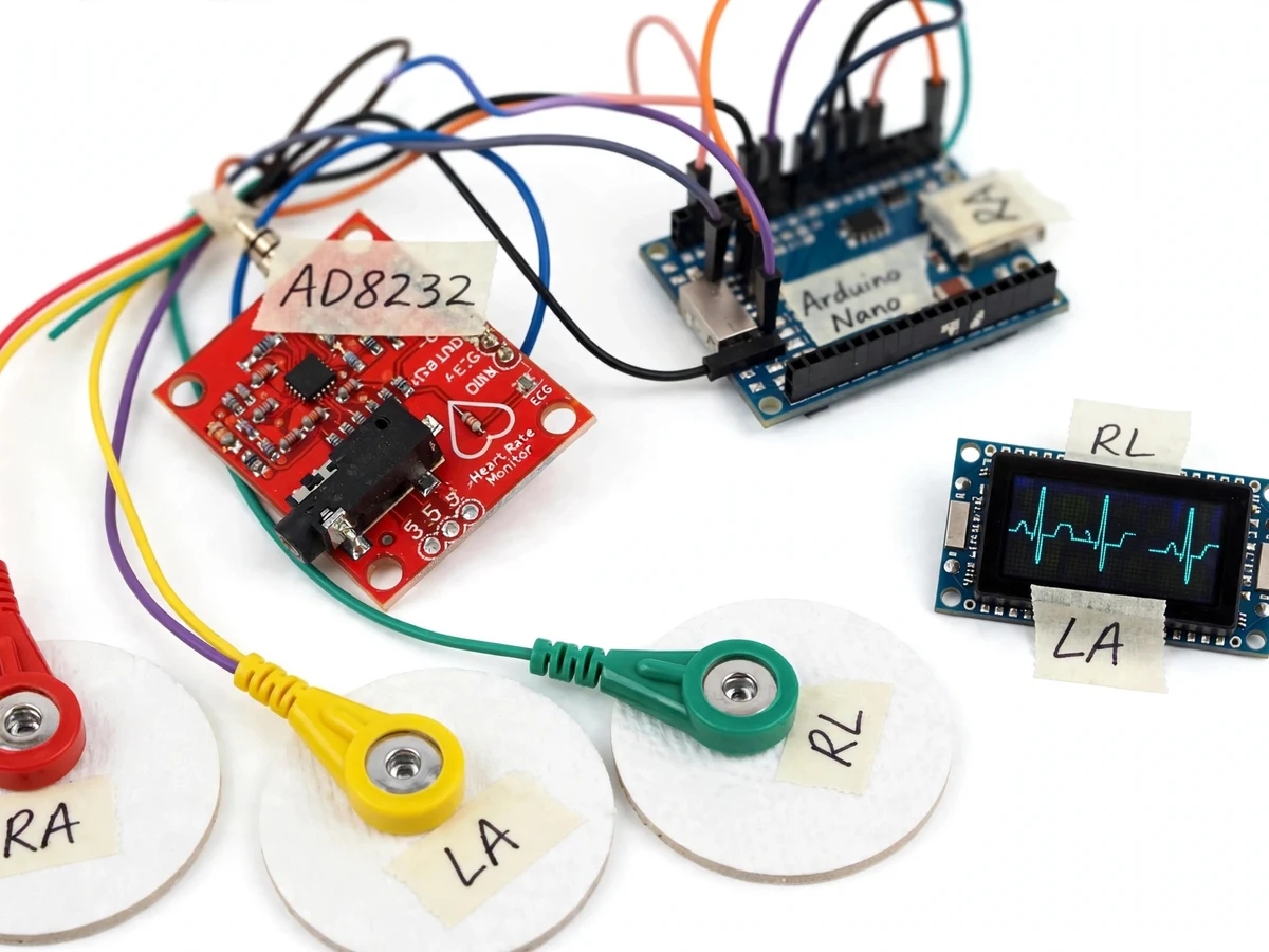
The heart's electrical activity is a millivolt-level signal buried in noise — mains hum, muscle artifacts and electrode motion all dwarf it, which is why measuring it cleanly is a genuine instrumentation challenge. The AD8232 was designed exactly for this: an integrated analog front-end with an instrumentation amplifier, filters and lead-off detection for single-lead ECG. This project builds a working heart monitor around it: disposable electrodes feed the AD8232, an Arduino samples the conditioned signal, an OLED draws the scrolling ECG trace in real time, and firmware detects R-peaks to compute beats per minute. The student sees their own PQRST complex appear on the display, measures their own heart rate, and writes a report on the signal chain that produced it — with the explicit, honest boundary that this is a teaching prototype, not clinical equipment.
How it works
- Three disposable electrodes are placed on the chest/arms per the guide; skin preparation reduces contact impedance.
- The AD8232 amplifies the differential biopotential (instrumentation amplifier), applies high-pass filtering to remove baseline drift and low-pass filtering to remove high-frequency noise.
- The Arduino's ADC samples the conditioned analog output at approximately 200 Hz.
- Firmware draws the samples as a scrolling waveform on the OLED while a peak-detection algorithm identifies R-peaks.
- Heart rate is computed from the R-R interval over a rolling window and shown on the display.
- If an electrode detaches, the AD8232 lead-off detection flags it and the display shows a lead-off warning.
Tech stack:
- AD8232 single-lead ECG front-end module
- Arduino Nano (ATmega328P)
- 0.96-inch OLED display (live waveform)
- Disposable ECG electrodes + snap leads
- R-peak detection firmware
- Serial logging for report plots
- Arduino IDE (C/C++ firmware)
| Parameter | Value |
|---|---|
| Leads | Single-lead (3 electrodes: RA, LA, RL drive) |
| Front-end | AD8232: instrumentation amp + filters (datasheet) |
| Sampling | Approximately 200 Hz, 10-bit ADC (design target) |
| Heart-rate range | Approximately 40–180 BPM display (expected) |
| Display | 0.96-inch OLED: scrolling trace + BPM + status |
| Lead-off | Hardware detection via AD8232 LO pins |
| Supply | 3.3 V (module), USB-powered logic |
| Logging | Serial stream of raw ADC samples |
Project features
- [AD8232 analog front-end] Integrated instrumentation amplifier with high-pass and low-pass filtering extracts the millivolt ECG signal from electrode noise.
- [Live OLED waveform] The Arduino samples the conditioned signal and draws a scrolling real-time ECG trace on a 0.96-inch OLED.
- [Heart-rate calculation] Firmware detects R-peaks with a threshold algorithm and computes BPM over a rolling window, displayed beside the trace.
- [Lead-off detection] The AD8232's lead-off pins flag a detached electrode; the display shows a clear warning instead of a flat line.
- [Right-leg-drive noise rejection] The AD8232's driven-reference output reduces mains interference, demonstrating a real biomedical noise-rejection technique.
- [Serial ECG logging] Raw samples stream over serial for plotting the PQRST complex in the report.
- [Electrode placement guide] Documented three-electrode placement with skin-preparation notes the student follows for clean traces.
What is included
- Working ECG monitor prototype (AD8232 module, Arduino, OLED, electrode leads)
- Arduino firmware with waveform plot, BPM and lead-off handling
- Wiring diagram and electrode-placement guide
- Skin-preparation and noise-reduction notes
- Project report PDF (ECG physiology basics, instrumentation amplifiers, filtering, sample traces template)
- PPT presentation for final review
- Viva Q&A preparation document
Limitations & prerequisites
- Educational prototype only — NOT a medical device; it must never be used for diagnosis, screening or any clinical decision. This boundary is stated in the report.
- Single-lead only; it cannot produce the 12-lead views a clinician uses.
- Trace quality depends on electrode contact, skin preparation and stillness — motion artifacts are expected and documented as a limitation.
- Mains interference is reduced, not eliminated; the demo works best away from heavy electrical noise.
- Heart-rate is computed from a simple threshold algorithm; arrhythmia detection is explicitly out of scope.
- Disposable electrodes are consumables and must be replaced between subjects for hygiene.
Frequently Asked Questions
Can this diagnose heart problems?
No — absolutely not. It is an educational electronics prototype that shows the ECG waveform and computes a simple heart rate. It is not calibrated, not certified, and must never be used for any medical decision. The report states this explicitly.
Why is the signal so hard to measure?
The heart's surface signal is around a millivolt, while mains hum and muscle noise are larger. The AD8232's instrumentation amplifier rejects common-mode noise and its filters remove drift and high-frequency junk — that signal chain is the project's core lesson.
What will I see on the display?
A scrolling waveform showing the P wave, QRS complex and T wave of your own heartbeat, plus your heart rate in BPM computed from the R-peaks.
Why three electrodes for a single lead?
Two sense the differential signal; the third provides the right-leg-drive reference that actively cancels common-mode interference — a standard biomedical technique.
What affects trace quality?
Electrode contact, skin preparation, subject stillness and nearby electrical noise. The guide covers all four, and motion artifacts are discussed honestly as a limitation.
Is this project suitable for a final-year project?
Yes — for Electronics, Biomedical and Instrumentation programs. It demonstrates instrumentation amplifiers, biopotential filtering and real-time signal processing, with clear educational-only boundaries. Suitable for B.E./B.Tech final-year projects in Electronics and Communication, Biomedical and Instrumentation.
Components & software requirements
- AD8232 single-lead ECG front-end module
- Arduino Nano (ATmega328P)
- 0.96-inch OLED display (live waveform)
- Disposable ECG electrodes + snap leads
- R-peak detection firmware
- Serial logging for report plots
- Arduino IDE (C/C++ firmware)
Delivery information
Built-to-order project. Delivery timeline is shared after order confirmation based on current queue.
Support terms
Complete documentation, setup guide, and viva preparation included. Support for setup and explanation provided.