
More project photos (2)
The problem
Testing any analog circuit — a filter's cutoff, an amplifier's bandwidth, a receiver's response — starts with injecting a known signal, which is why the function generator is a bench staple. Classical generators build waveforms with RC oscillators or 555 timers, but their frequency drifts with temperature and component tolerance, and tuning is coarse. Direct digital synthesis takes the digital approach: a phase accumulator advances through a sine lookup table at a programmable rate, and a DAC converts the samples to analog — the output frequency is set by a digital tuning word referenced to a stable crystal, so it is as accurate as the clock and changes in microhertz steps. The AD9833 packages this whole engine in a cheap module. This project wraps it in a complete instrument: Arduino control over SPI, encoder-based frequency entry, OLED display, waveform selection and a sweep mode that ramps frequency automatically for response testing.
How it works
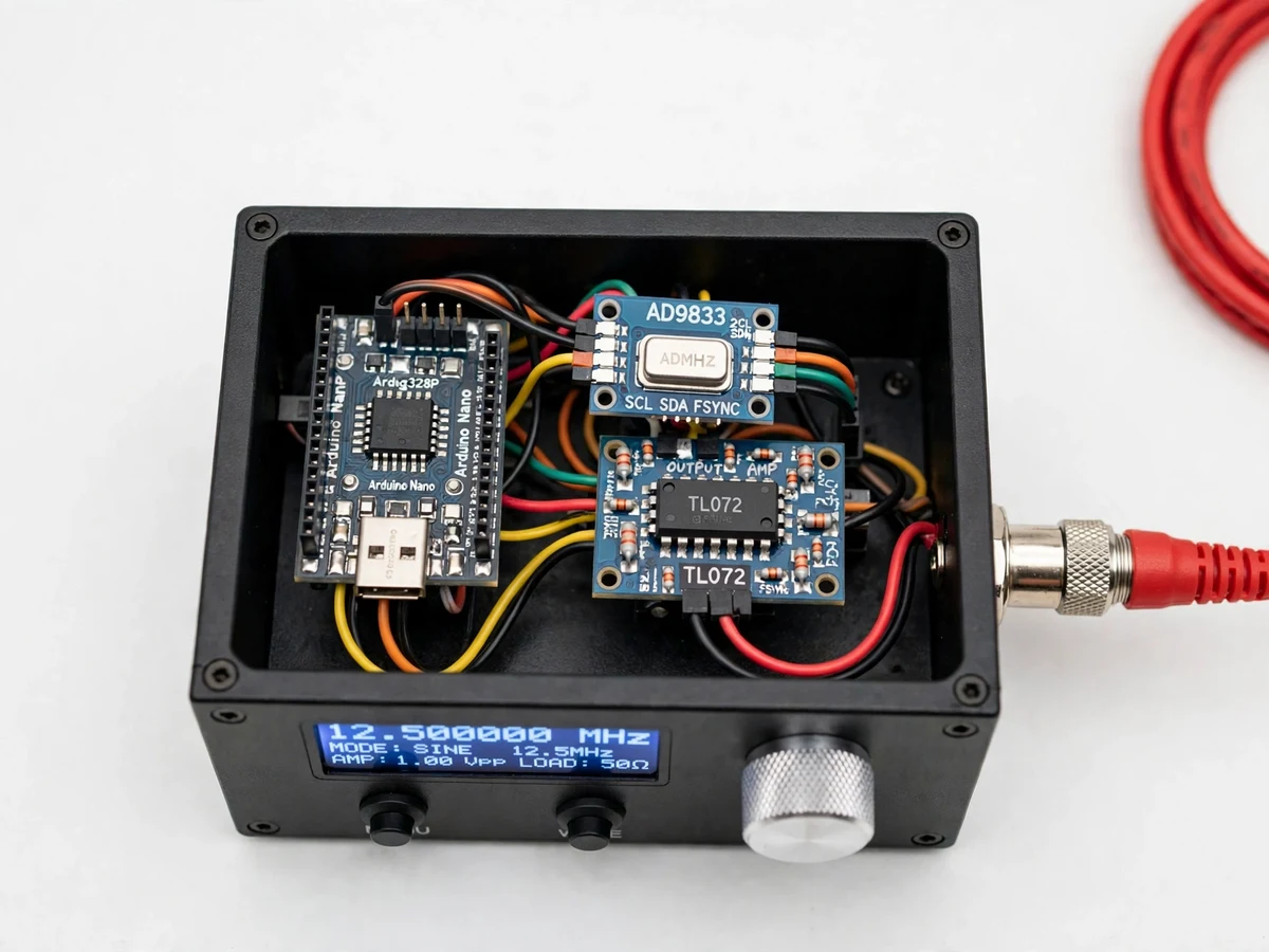
- The Arduino communicates with the AD9833 over SPI, writing a 28-bit frequency tuning word computed from the desired output frequency and the module's reference clock.
- Inside the AD9833, a phase accumulator advances by the tuning word each clock; its upper bits address a sine lookup table whose samples feed the on-chip DAC.
- For square output the DDS sign bit is used; triangle is derived in the module's waveform modes — selected by control-register bits from the firmware.
- The raw DAC output passes through the op-amp conditioning stage for buffering and amplitude adjustment to the BNC output.
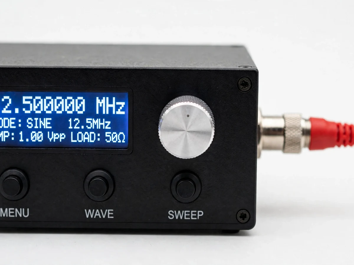
- The rotary encoder and its push-button navigate a simple menu (frequency, waveform, sweep start/stop/rate); the OLED renders the current state.
- In sweep mode the firmware steps the tuning word linearly between the start and stop frequencies, dwelling per the set rate, and shows the instantaneous frequency.
- Presets are saved to EEPROM and restored at power-up.
Tech stack:
- Arduino Uno/Nano (ATmega328P)
- AD9833 DDS waveform generator module (SPI)
- Rotary encoder with push-button
- OLED display (I2C)
- Op-amp output buffer/gain stage
- Arduino IDE (C/C++ firmware)
- BNC output connector and test leads
| Parameter | Value |
|---|---|
| DDS core | AD9833 module, SPI-controlled, 28-bit tuning word |
| Waveforms | Sine, triangle, square (per AD9833 capabilities) |
| Frequency range | 0.1 Hz – 12.5 MHz (AD9833 datasheet range; usable amplitude rolls off near the top, documented) |
| Frequency setting | Digital steps via rotary encoder; crystal-referenced accuracy |
| Sweep | Configurable start/stop frequency and sweep rate in firmware |
| Output | Buffered through op-amp stage; amplitude adjustable (exact levels in build notes) |
| Display | OLED: frequency, waveform, sweep status, menu |
| Memory | EEPROM preset storage, restored at power-up |
Project features
- [DDS waveform engine] The AD9833's phase accumulator and 10-bit DAC generate sine, triangle and square waves with crystal-referenced accuracy — the DDS principle demonstrated in hardware.
- [Wide frequency range] 0.1 Hz to 12.5 MHz in fine digital steps (per the AD9833 datasheet), covering audio, ultrasonic and RF-experiment ranges from one instrument.
- [Frequency sweep mode] The firmware ramps the output between configurable start/stop frequencies at a set rate, so a filter or amplifier's response can be observed sweeping live on an oscilloscope.
- [Rotary encoder UI] A rotary encoder with push-select sets frequency, waveform and sweep parameters digit by digit — a proper instrument interface, not trim pots.
- [OLED readout] A clear OLED shows frequency, waveform type, and sweep status at a glance.
- [Output conditioning stage] An op-amp buffer/gain stage presents the DDS output at a usable level with adjustable amplitude, documented in the build notes.
- [Preset memory] Frequently used frequency/waveform combinations can be stored and recalled, demonstrating EEPROM use in instruments.
What is included
- Working DDS signal generator prototype (Arduino, AD9833 module, encoder, OLED, output stage, enclosure)
- Complete firmware source code (SPI driver, tuning-word math, menu UI, sweep engine, presets)
- Circuit and wiring documentation
- Component list with ratings
- Setup and verification procedure (buyer-run: verify output on oscilloscope/CRO across the range)
- Project report PDF (DDS theory, phase accumulator, AD9833 architecture, methodology, test procedure)
- PPT presentation for final review
- Viva Q&A preparation document (DDS vs analog oscillators, tuning word, Nyquist limit in DDS, sweep use)
- Setup and demonstration guide
Limitations & prerequisites
- This is an academic bench instrument, not calibrated test equipment; frequency accuracy follows the module's crystal and amplitude is approximate.
- The AD9833's 10-bit DAC and 12.5 MHz ceiling bound waveform purity near the top of the range — harmonic content there is a documented characteristic, not measured at build.
- Output amplitude and offset ranges are design values of the conditioning stage, verified by the buyer's own oscilloscope checks.
- Square-wave rise time is limited by the op-amp stage; RF-grade edges are out of scope.
- Single-ended output only; differential or modulated outputs are possible extensions.
Frequently Asked Questions
What is DDS and why is it better than a 555-based generator?
Direct digital synthesis builds the waveform from a digital phase accumulator referenced to a crystal, so frequency is precise, drift-free and settable in tiny steps. A 555/RC oscillator drifts with temperature and tunes coarsely.
What frequencies and waveforms does it produce?
Sine, triangle and square from 0.1 Hz to 12.5 MHz per the AD9833 datasheet, with the usable amplitude rolling off near the top as documented.
What is the sweep mode for?
It ramps frequency automatically between two set points — connect the output through a filter to an oscilloscope and watch the filter's response sweep live, which is how bandwidth is found experimentally.
How is the frequency set?
With a rotary encoder driving a menu on the OLED — digit-by-digit entry plus presets stored in EEPROM.
What are the main limitations?
Hobby-instrument grade, not calibrated; amplitude approximate; harmonic content rises near the 12.5 MHz ceiling; single-ended output.
Is this project suitable for a final-year project?
Yes — for Electronics and Communication programs. DDS theory, SPI interfacing, the Nyquist constraint and instrument UI design are strong viva topics. Suitable for B.E./B.Tech final-year projects in Electronics and Communication engineering.
Components & software requirements
- Arduino Uno/Nano (ATmega328P)
- AD9833 DDS waveform generator module (SPI)
- Rotary encoder with push-button
- OLED display (I2C)
- Op-amp output buffer/gain stage
- Arduino IDE (C/C++ firmware)
- BNC output connector and test leads
Delivery information
Built-to-order project. Delivery timeline is shared after order confirmation based on current queue.
Support terms
Complete documentation, setup guide, and viva preparation included. Support for setup and explanation provided.