
More project photos (2)
The problem
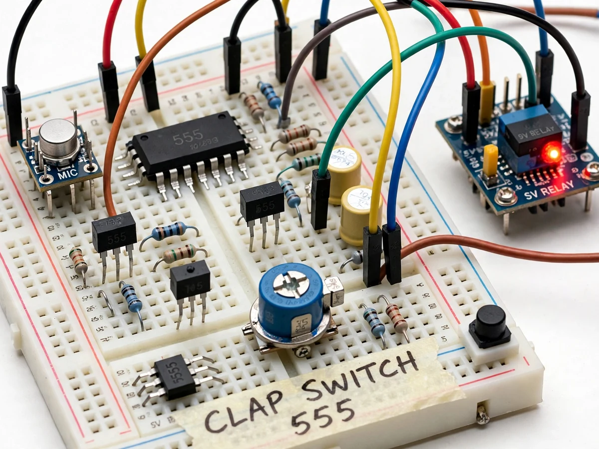
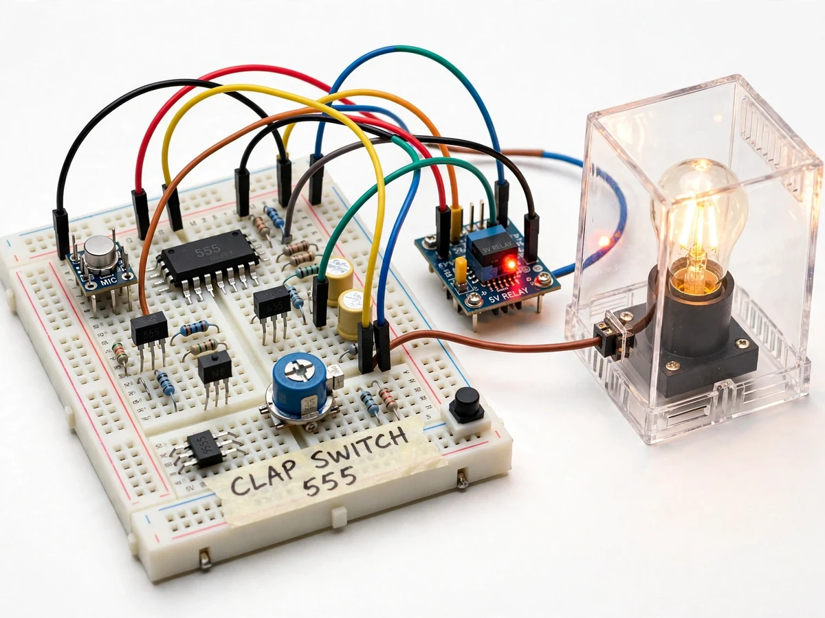
Before microcontrollers absorbed every small control task, circuits like this one taught the core analog skills: transducing sound to electricity, amplifying a millivolt signal cleanly, and using a timer IC as a logic element. The clap switch is the canonical example — it is genuinely useful (hands-free switching for a bedside lamp or a workshop light) and every stage is observable on an oscilloscope: the microphone's burst, the amplified pulse, the flip-flop toggling, the relay clicking. The 555 timer, wired in bistable mode, is the heart of it: each detected clap pulse flips its output state, and the output drives a transistor-relay stage that handles the mains lamp. This project builds the complete circuit on a proper PCB/breadboard layout with sensitivity tuning and noise immunity designed in, not as an afterthought.
How it works
- A clap produces a sharp acoustic transient; the electret microphone converts it to a small electrical burst.
- The two-stage transistor preamplifier boosts the burst to several volts while the coupling capacitors block DC and low-frequency hum.
- The pulse-shaping stage cleans the amplified burst into a single crisp trigger pulse, rejecting ringing and background noise.
- The trigger pulse hits the 555 wired in bistable mode, which flips its output state — low to high on the first clap, high to low on the next.
- The 555 output drives a transistor that energizes the relay coil; the relay contacts switch the mains lamp, and a flyback diode clamps the coil's back-EMF.
- An LED mirrors the output state so the switching is visible even with the lamp disconnected.
- The sensitivity preset sets the trigger threshold; the manual override button forces the state directly.
Tech stack:
- 555 timer IC (bistable configuration)
- Electret condenser microphone
- Transistor preamplifier stages (general-purpose NPN)
- Pulse-shaping / trigger conditioning stage
- Relay output stage with transistor driver and flyback diode
- Mains lamp demo load with proper enclosure
- Regulated 5–9 V DC supply
| Parameter | Value |
|---|---|
| Core IC | 555 timer in bistable (flip-flop) mode |
| Input | Electret condenser microphone with bias network |
| Amplification | Two-stage transistor preamp; gain set by design (values in build notes) |
| Triggering | Pulse-shaped transient detection with adjustable threshold (sensitivity preset) |
| Output | Relay contacts switching a mains lamp (relay rating per datasheet; demo lamp within rating) |
| Indication | LED mirroring output state |
| Override | Manual pushbutton forces output state |
| Supply | Regulated low-voltage DC for the circuit; mains only at the relay contacts |
Project features
- [Electret microphone front-end] An electret condenser mic with biasing converts the clap's acoustic burst into a millivolt-level electrical signal.
- [Transistor preamplifier] A two-stage transistor amplifier raises the mic signal to logic-usable levels, with gain set so sharp transients pass and ambient hum does not.
- [555 bistable toggle] The 555 timer wired in bistable (flip-flop) mode toggles its output on each trigger pulse — the classic no-microcontroller toggle logic.
- [Relay output stage] A transistor-driven relay switches a mains lamp load, with a flyback diode protecting the driver — proper mains-switching practice.
- [Sensitivity control] A preset potentiometer sets the trigger threshold, so the student can demonstrate the trade-off between missed claps and false triggering.
- [Noise-immunity design] A pulse-shaping stage (RC + Schmitt-style conditioning) rejects slow ambient noise and mains hum, responding only to sharp transients like claps.
- [Manual override] A pushbutton forces the output on or off directly, so the lamp stays usable when clapping is not convenient.
What is included
- Working clap-switch prototype (mic, amplifier, 555 toggle stage, relay, lamp, enclosure)
- Complete circuit diagrams with component values and design notes
- Component list with ratings
- Setup and sensitivity-tuning procedure (buyer-run: set threshold, verify noise immunity)
- Project report PDF (transducer, amplification, 555 bistable theory, relay driving, methodology)
- PPT presentation for final review
- Viva Q&A preparation document (555 bistable vs monostable vs astable, electret biasing, flyback diode, noise immunity)
- Setup and demonstration guide
Limitations & prerequisites
- This is an academic demonstration circuit; the mains side must stay inside its enclosure and be wired with proper insulation and earthing practice.
- Detection range is a design characteristic of the mic gain and threshold — a few meters in a quiet room is typical; noisy environments need re-tuning, demonstrated as the sensitivity trade-off.
- It responds to any sharp transient (door slam, book drop), not only claps — this is inherent to amplitude-based detection and documented as a limitation.
- Relay contacts have a finite electrical life per the datasheet; rapid repeated toggling is a demo-only behavior.
- No microcontroller or wireless control in the base build; those are noted extensions.
Frequently Asked Questions
How does the 555 toggle the lamp?
The 555 is wired in bistable mode — a flip-flop. Each trigger pulse from the sound stage flips its output: first clap sets it high (relay on), next clap resets it low (relay off).
Won't background noise trigger it?
The sensitivity preset sets a threshold, and the pulse-shaping stage passes only sharp transients while rejecting hum and slow noise. Tuning that trade-off is part of the documented setup.
What switches the mains lamp?
A relay driven by a transistor from the 555 output, with a flyback diode across the coil. The low-voltage circuit never touches mains directly.
Can I also switch it manually?
Yes — a manual override pushbutton forces the output state for times when clapping is impractical.
What are the main limitations?
Any sharp sound can trigger it (amplitude detection, not pattern recognition); range is a few meters and environment-dependent; demo circuit, not a certified mains product.
Is this project suitable for a final-year project?
Yes — for Electronics programs as a mini-project or a module of a larger build. The 555 modes, analog signal chain and relay driving are fundamental viva topics. Suitable for B.E./B.Tech final-year projects in Electronics and Communication engineering.
Components & software requirements
- 555 timer IC (bistable configuration)
- Electret condenser microphone
- Transistor preamplifier stages (general-purpose NPN)
- Pulse-shaping / trigger conditioning stage
- Relay output stage with transistor driver and flyback diode
- Mains lamp demo load with proper enclosure
- Regulated 5–9 V DC supply
Delivery information
Built-to-order project. Delivery timeline is shared after order confirmation based on current queue.
Support terms
Complete documentation, setup guide, and viva preparation included. Support for setup and explanation provided.