
More project photos (2)
The problem
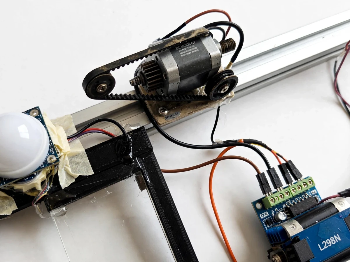
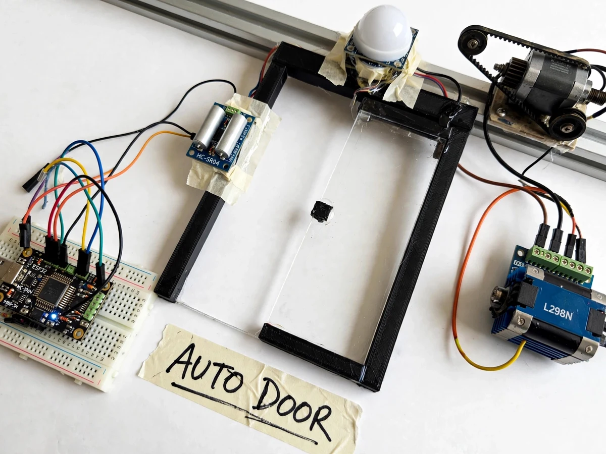
Automatic doors are taken for granted in malls and hospitals, but the control problem behind them is a good embedded project: detect approach, drive the door, never close on a person, and handle the motor safely. This project builds that system at model scale: a PIR motion sensor watches the approach zone, an ESP32 drives a DC gear motor through an L298N driver to slide a model door panel along its rail, and an HC-SR04 ultrasonic sensor guards the closing path — if it sees an obstacle while closing, the door immediately reverses. Limit switches mark the fully-open and fully-closed positions so the motor never stalls at the ends, and a manual push button gives fallback control. The LCD shows the door state (OPENING / OPEN / CLOSING / CLOSED / OBSTACLE) at all times.
How it works
- The PIR sensor detects motion in the approach zone and signals the ESP32; the state machine moves from IDLE to OPENING.
- The ESP32 drives the L298N to run the gear motor, sliding the door panel along the rail until the open limit switch trips.
- The door holds open for the configured time (default approximately 5 seconds), retriggered by continued PIR activity.
- On hold expiry with no motion, the state machine moves to CLOSING; the ultrasonic sensor continuously scans the door path.
- If the ultrasonic sensor detects an obstacle during closing, the door immediately reverses to OPEN and the LCD shows "OBSTACLE"; otherwise it closes until the closed limit switch trips.
- Limit switches cut the motor at both ends of travel; a software timeout backs this up in case a switch ever fails.
- The manual button forces an open/close cycle directly, and the cycle counter on the LCD increments with every completed open-close.
Tech stack:
- ESP32 development board
- Arduino IDE (C/C++ firmware)
- PIR motion sensor module (approach trigger)
- HC-SR04 ultrasonic sensor (safety, approximately 2–400 cm)
- DC gear motor with belt drive on a rail
- L298N motor driver module
- Microswitch limit switches (open + closed ends)
- 16x2 LCD with I2C backpack
- Push button for manual override
- Model sliding-door frame on rail track
| Parameter | Value |
|---|---|
| Controller | ESP32, 3.3 V logic |
| Approach sensor | PIR, adjustable sensitivity and retrigger |
| Safety sensor | HC-SR04 ultrasonic, approximately 2–400 cm range |
| Motor | DC gear motor, belt-driven slide |
| Driver | L298N, direction + PWM speed control |
| End stops | 2 microswitch limit switches + software timeout backup |
| Hold-open time | Approximately 5 seconds (configurable) |
| Display | 16x2 LCD (I2C): state, warnings, cycle count |
| Power | 5 V logic + separate motor supply per driver rating |
Project features
- [PIR approach detection] A PIR motion sensor with an adjustable dome watches the approach zone and triggers the open cycle when a person nears.
- [Motorized sliding drive] A DC gear motor with belt drive slides the door panel along the rail; the L298N driver gives direction and speed control from the ESP32.
- [Ultrasonic safety reversal] An HC-SR04 watches the closing path — if anything enters it while the door closes, the door reverses to open immediately instead of continuing.
- [Limit-switch end stops] Microswitches at both rail ends mark fully-open and fully-closed, so the motor stops on position, never by stalling.
- [State-machine control] The firmware runs a clean state machine (IDLE → OPENING → OPEN → CLOSING → CLOSED, plus OBSTACLE reverse) with a configurable hold-open time.
- [Manual override button] A push button opens/closes the door directly for maintenance or fallback, independent of the PIR.
- [Live status LCD] A 16x2 LCD shows the current state, obstacle warnings and cycle count.
What is included
- Working prototype: model sliding door frame on rail, PIR, ultrasonic sensor, gear motor with belt, L298N, limit switches, LCD, button
- Complete ESP32 firmware (state machine, motor control, safety reversal, limit handling, LCD)
- State-machine diagram documenting all states and transitions
- Wiring diagram and connection table
- Sensor positioning and sensitivity tuning guide
- Project report PDF (background, state-machine design, safety logic, methodology, working, results)
- PPT presentation for final review
- Viva Q&A preparation document (state machines, H-bridge driving, ultrasonic sensing, limit switches, safety design)
Limitations & prerequisites
- Model scale: the rail, panel and motor demonstrate the control system at desk size — a full-size door needs a rated operator and is installation work outside the scope.
- The PIR detects motion, so a person standing perfectly still in the approach zone may not retrigger the hold-open; the ultrasonic safety sensor still guards the closing path.
- The ultrasonic sensor's effective safety zone is limited to its beam and range; the setup guide covers positioning it to cover the door path.
- Motor speed is a demo-scale setting; real doors need controlled acceleration profiles (listed as future scope).
- The software timeout is a backup for limit-switch failure, not a substitute for the switches — both are documented as a layered design.
Frequently Asked Questions
How does the door know when to open?
A PIR motion sensor watches the approach zone. When it detects movement, the ESP32 starts the open cycle and drives the gear motor until the open limit switch trips.
What stops it closing on someone?
An HC-SR04 ultrasonic sensor scans the closing path. If it detects an obstacle while closing, the firmware immediately reverses the door to open and shows an OBSTACLE warning on the LCD.
What are the limit switches for?
Microswitches at both ends of the rail tell the controller exactly when the door is fully open or fully closed, so the motor stops on position instead of stalling. A software timeout backs them up.
Can it be opened manually?
Yes — a push button forces an open/close cycle directly, independent of the PIR sensor, for maintenance or fallback.
How long does it stay open?
Approximately 5 seconds by default, retriggered by continued motion in the approach zone; the hold time is configurable in firmware.
Is this project suitable for a final-year project?
Yes — for IoT & Embedded programs. It is a proper state-machine control build with a documented safety layer (sensors + limit switches + timeout), motor driving and live status display. Suitable for B.E./B.Tech final-year projects in IoT & Embedded.
Components & software requirements
- ESP32 development board
- Arduino IDE (C/C++ firmware)
- PIR motion sensor module (approach trigger)
- HC-SR04 ultrasonic sensor (safety, approximately 2–400 cm)
- DC gear motor with belt drive on a rail
- L298N motor driver module
- Microswitch limit switches (open + closed ends)
- 16x2 LCD with I2C backpack
- Push button for manual override
- Model sliding-door frame on rail track
Delivery information
Built-to-order project. Delivery timeline is shared after order confirmation based on current queue.
Support terms
Complete documentation, setup guide, and viva preparation included. Support for setup and explanation provided.